5-40 Electrical Connections Rexroth EcoDrive Cs Drives
DOK-ECODR3-DKC**.3-CS*-PR02-EN-P
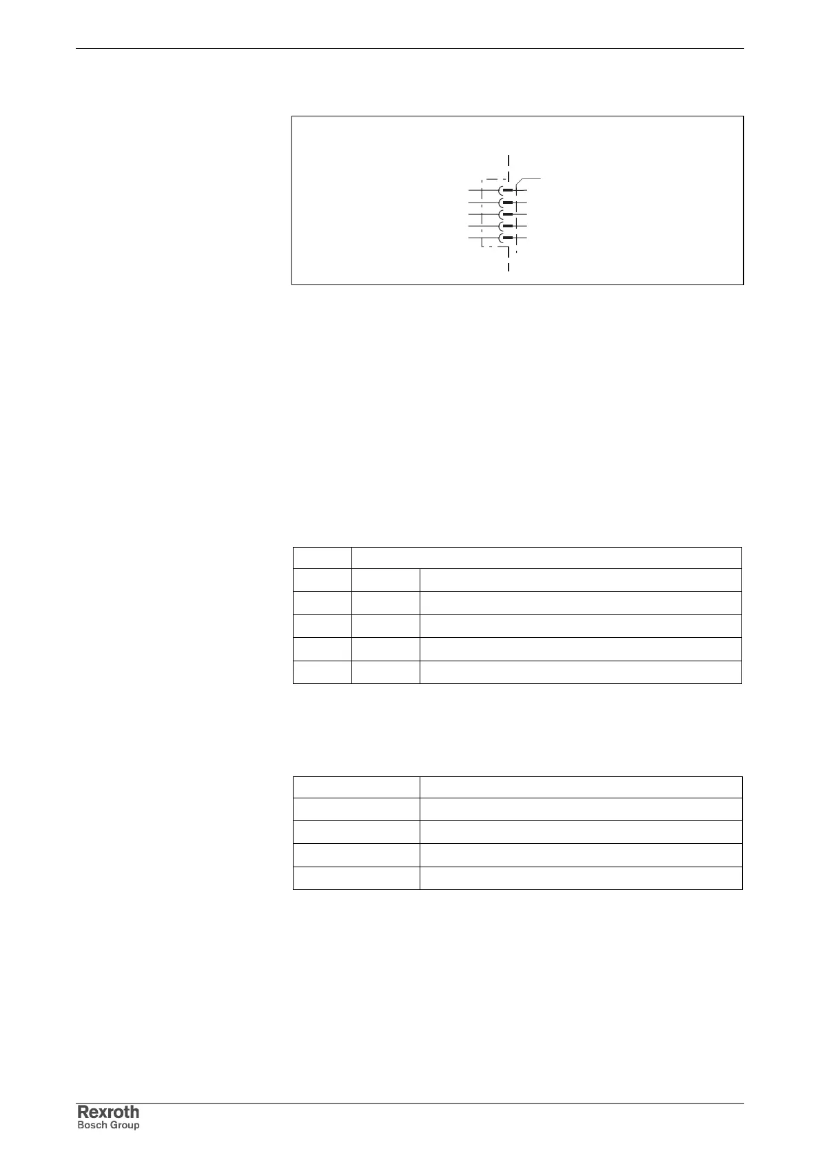
Connection Diagram for DeviceNet Interface
devicenet_anschluss.FH7
DeviceNet Interface
V-
CAN-
CAN+
V+
1
2
3
4
5
device-external device-internal
shield
Fig. 5-78: Connection
as per DeviceNet specification 2.0 Vol. 1
Open Screw Connector
as per DeviceNet specification 2.0 Vol. 1, appendix B
as per DeviceNet specification 2.0 Vol. 1, appendix B
terminating resistor: 121 Ohm, 1%, ¼ W
as per DeviceNet specification 2.0 Vol. 1
Pin Definition
1V- 0 V
2 CAN- differential signal
3 shield shield connection
4 CAN+ differential signal
5 V+ interface supply
Fig. 5-79: Assignment of the interface signals
+30 V
Bus voltage Current consumption
11 V 70 mA
18 V 45 mA
24 V 35 mA
32 V 28 mA
Fig. 5-80: Current consumption via bus connector
For the definition of the diagnostic displays please see the Functional
Description of the respective firmware.
DeviceNet Interface Connection
Compatibility of the Interface
Recommended Cable Type
Connections of the Bus Nodes
Baud Rate and Cable Length
Pin Configuration of the Plug-In
Connector
Maximum Bus Voltage
Current Consumption on the
Bus
Diagnostic Displays
H60 – H65
Courtesy of CMA/Flodyne/Hydradyne ▪ Motion Control ▪ Hydraulic ▪ Pneumatic ▪ Electrical ▪ Mechanical ▪ (800) 426-5480 ▪ www.cmafh.com