5-44 Electrical Connections Rexroth EcoDrive Cs Drives
DOK-ECODR3-DKC**.3-CS*-PR02-EN-P
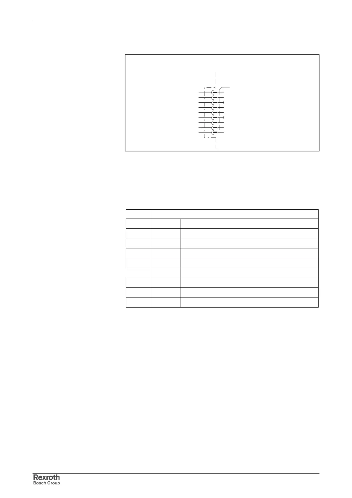
Connection Diagram for CANopen Interface
canopen_anschluss.FH7
CANopen Interface
n.c.
CAN_L
0V
n.c.
0V
CAN_H
n.c.
n.c.
1
2
3
4
5
6
7
8
9
shield
device-external device-internal
Fig. 5-90: Connection
as per ISO 11 898
as per ISO 11 898
Pin Definition
1 n.c. n.c.
2 CAN_L differential signal
30V Gnd
4 n.c. n.c.
5 shield shield connection
60V 0V
7 CAN_H differential signal
8 n.c. n.c.
9 n.c. n.c.
Fig. 5-91: Assignment of the interface signals
Via D-subminiature screws and metallized connector housing.
For the definition of the diagnostic displays please see the Functional
Description of the respective firmware.
CANopen Interface Connection
Compatibility of the Interface
Recommended Cable Type
Pin Configuration of the X50
Plug-In Connector
Shield Connection
Diagnostic Displays
H50 – H55
Courtesy of CMA/Flodyne/Hydradyne ▪ Motion Control ▪ Hydraulic ▪ Pneumatic ▪ Electrical ▪ Mechanical ▪ (800) 426-5480 ▪ www.cmafh.com