SYNAX200 Set-Up SYNAX200 Ring 8-7
DOK-SYNAX*-SY*-07VRS**-PR01-EN-P
X12
X11R
X
H3 ERR
X10T
X
S3HIG
H
S2LO
W
Read and follow
Instructions for Electrical Drives"
manual,
DOK-GENERL-DRIVE******-SVS...
DANG
High oltage.
Danger of electrical shock.
Do not touch electrical connections
fo
5 minutes after switching
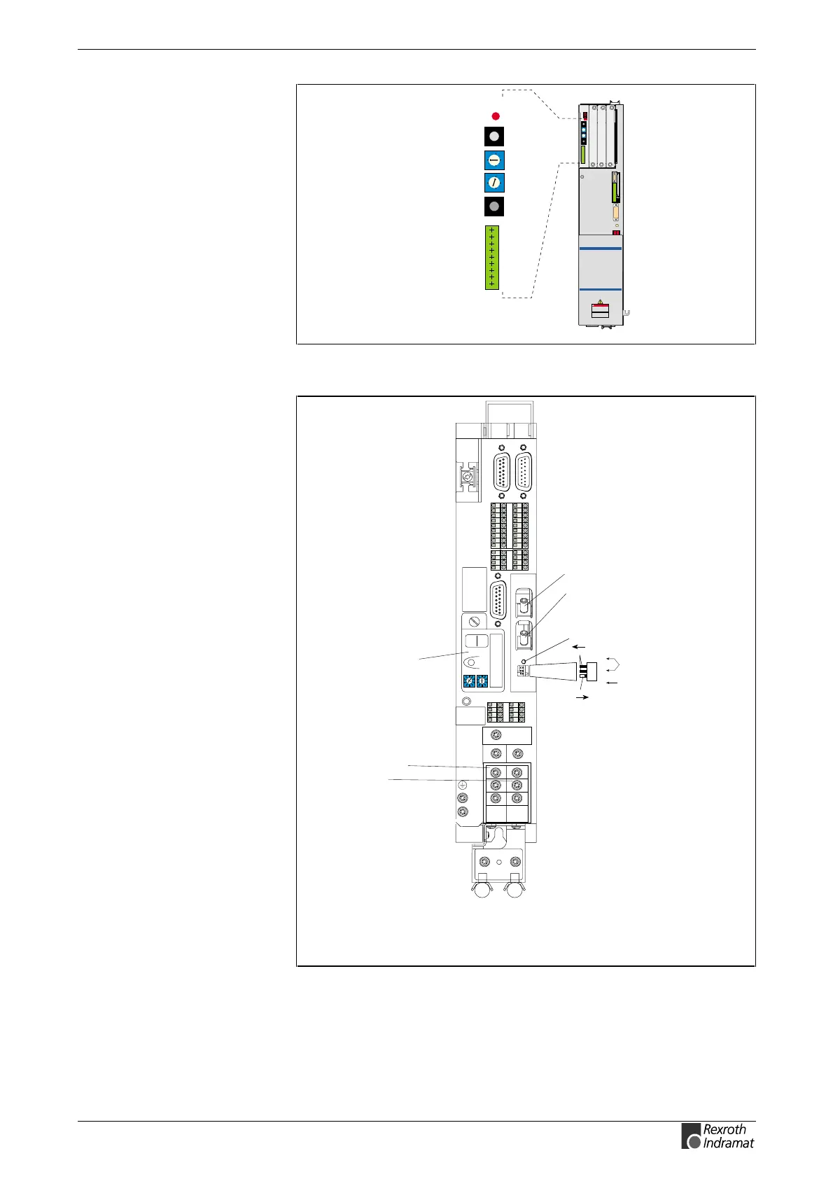
H3 ERR distortion display
X10 fibre-optic transmitter
for SERCOS interface
X11 fibre-optic receiver
for SERCOS interface
SY7PR029.FH7
0
1
2
3
4
5
6
7
8
9
0
1
2
3
4
5
6
7
8
9
Fig. 8-13: Connections DSS 2.1 (DIAX03/DIAX04)
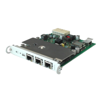
Power connection
Motor connection
DKC**.3-040-7-FW
Barcode
0
1
2
3
4
5
6
7
8
9
0
1
2
3
4
5
6
7
8
9
H1
S1
S3
S2
Barcode
Typenschild
123456789 1234
1112131415161718
5678
1234
5678
XE2
XE1
L+
L-
L1
L2
L3
A1
A2
A3
X7:
Programming module
(Firmware, Parameter)
H1 - Diagnosis indicator
S1 - Fault clearance button
S2, S3 - Adress switch
SY6PR070.FH7
3
2
1
ON
OFF
S20
H20
ERROR
3
2
1
X20
X21
TX
RX
Switch for setting the
transmitter power
Switch for setting the data rate
H20: distortion display
for SERCOS interface
X20: fibre-optic transmitter
X21: fibre-optic receiver
Fig. 8-14: Connections DKC02.3 (ECODRIVE03)