SYNAX200 PPC Motion Control Configuration 4-11
DOK-SYNAX*-SY*-07VRS**-PR01-EN-P
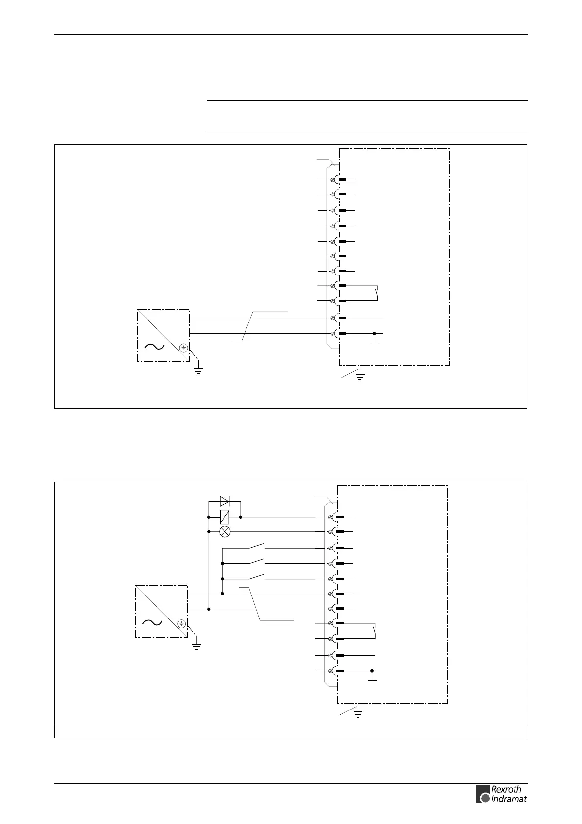
4.7 Connecting the Power Supply
Note: Connector and modules may only be inserted or removed
when the power is switched off.
9
8
7
6
5
1
2
10
11
3
4
0V
X1
Bb
+24VDC +/-20%
Bb
+24VDC
PPC-R
Power Supply Unit
0V
2x0,75 mm
2
0V external
24V external
Dig. input 3
Dig. input 2
Dig. input 1
Dig. output 2
Dig. output 1
Earthing
bolt
PPC-R_AnX1.FH7
Fig. 4-16: Connecting the power supply
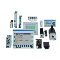
4.8 Connecting Inputs and Outputs
9
8
7
6
5
1
2
10
11
3
4
0V
X1
Bb
+24VDC +/-20%
Bb
+24VDC
PPC-R
Power supply unit
0V
2x0.75 mm
2
0V external
24V external
Dig. input 3
Dig. input 2
Dig. input 1
Dig. output 2
Dig. output 1
Earthing bolt
PPC-R_AnX1_EA.FH7
Fig. 4-17: Connecting inputs and outputs