SYNAX200 Determining the Control-Related Plug-In Cards 6-3
DOK-SYNAX*-SY*-07VRS**-PR01-EN-P
6.3 Determining the Master Axis
If it is necessary that the slave drive of the electronic gears has reference
to a real master axis, then a master axis encoder must be mounted to this
master axis.
Note: The master axis encoder must be mounted so that one master
axis revolution equals one machine cycle (1 product ejection).
This can be reached when parametrize a electronic measuring
gear if necessary (see DOK-SYNAX*-SY*-07VRS**-FK01-EN-
P, section 2.2 Real master axis - electronic measuring gear)
The master axis encoder is mounted to an encoder interface in the drive
amplifier. The master axis position is generated from the encoder signals
and transmitted via SERCOS interface to the PPC motion control.
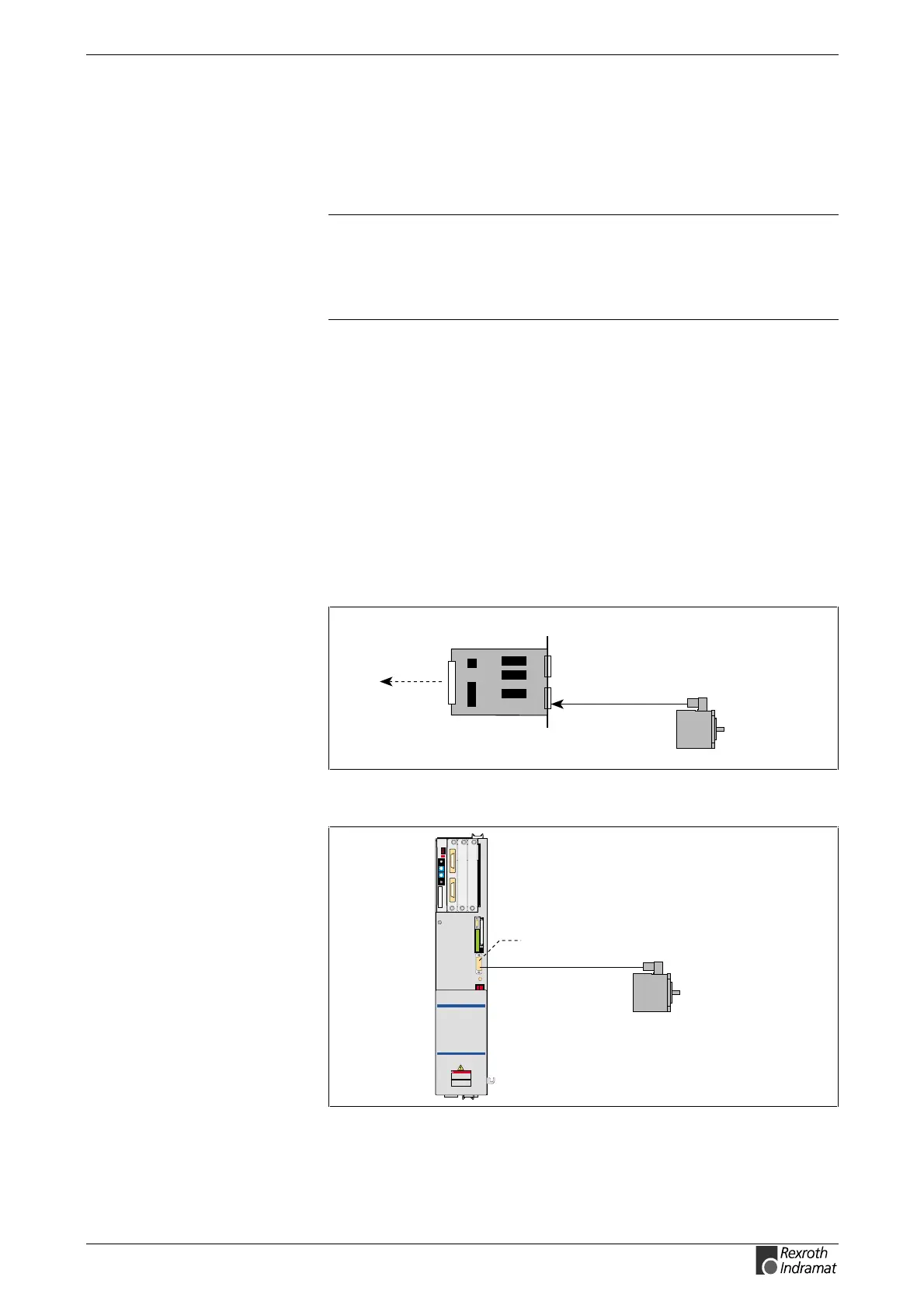
High-Resolution Singleturn Encoder GDS or Multiturn
Encoder GDM Made by Indramat
The singleturn encoder GDS or the multiturn encoder GDM is connected
via encoder interface DFF or DSF interface (connector X4) to a drive
amplifier.
The singleturn encoder GDS delivers an absolute encoder information
within one revolution, the multiturn encoder within 4096 revolutions.
SY7PR017.FH7
master axis encoder
GDS 1.1/GDM1.1
DFF
master axis position
in the slot of a
DKR/HDS
Fig. 6-4: GDS or GDM master axis encoder with encoder interface DFF
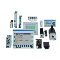
SY7PR018.FH7
Read and follow
Instructions for Electrical Drives"
manual,
DOK-GENERL-DRIVE******-SVS...
DANG
High oltage.
Danger of electrical shock.
Do not touch electrical connections
fo
5 minutes after switching
master axis encoder
GDS 1.1/GDM 1.1
X4
Fig. 6-5: GDS or GDM master axis encoder with DSF interface X4 (DIAX04)
DIAX03, DIAX04