SYNAX200 Determining the Control-Related Plug-In Cards 6-9
DOK-SYNAX*-SY*-07VRS**-PR01-EN-P
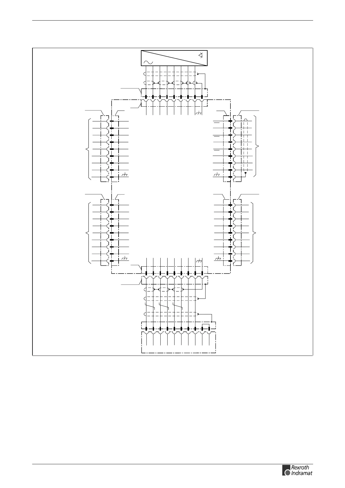
Terminal Diagram
Ap5242f1.fh7
DGA01.2
1 2 5
6 7 8
0V +8V
4 3 9
max. cable length: 75 m
INS0701
X2
A+ A- B+ B- R+ R-
7 8 6
5 4 3
0V +8V
10 2 1 12
A+ A- B+ B- R+ R-
A+
A-
B+
B-
R+
R-
0V
frei
DLF
INS0701
1
2
5
6
7
8
4
3
9
X4
A+
A-
B+
B-
R+
R-
0V
frei
DLF
INS0701
1
2
5
6
7
8
4
3
9
X5
3
4
5
6
8
1
10
12
9
U
a0
U
a0
U
a1
U
a1
U
a2
U
a2
INS0493
0V
frei
incremental encoder output
X6
A+
A-
B+
B-
R+
R-
0V
frei
INS0701
1
2
5
6
7
8
4
3
9
X3
to DLF position interface
Terminal X2 supplies the
DGA with power and must
always be there.
DLF
max. processing frequency
f
max
= 400 kHz
measuring sytem, e.g.,
LIF181, LS186, LS468
from Heidenhain
5 6 8
1 3 4 10 12 9
INS0488
X1
1V
SS
max. cable length: 30 m
0V +5V
A+ A- B+ B- R+ R-
Fig. 6-17: Terminal diagram DGA01.2