5-2 Determining Basic Drive Configuration SYNAX200
DOK-SYNAX*-SY*-07VRS**-PR01-EN-P
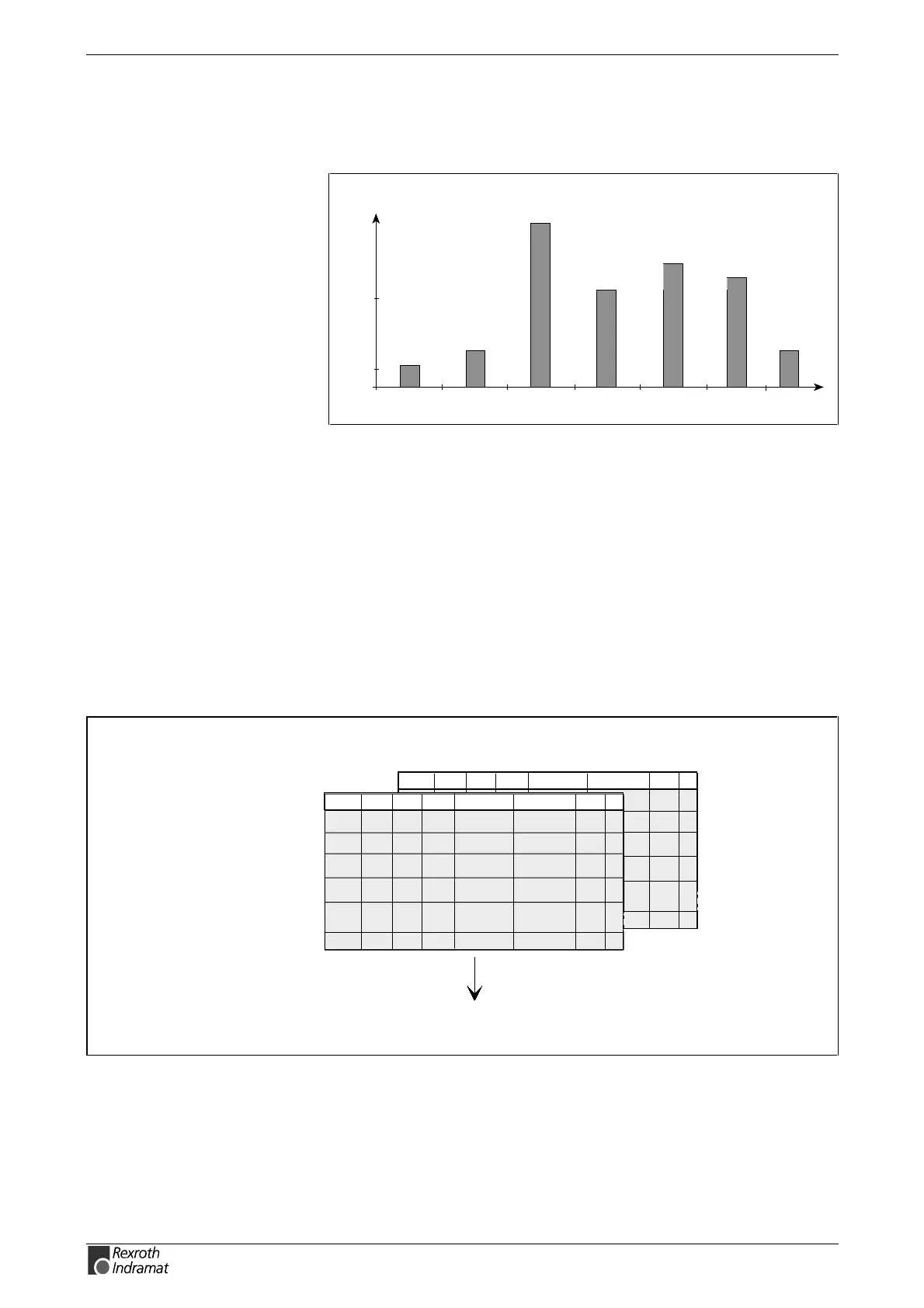
b) Selecting the Suitable Motor/Controller Combinations
The selection lists must be used. The following figure offers a rough
orientation.
SY7PR003.FH7
rated output
[KW]
10
50
MKD
12
20
2AD
93
1MB
55
MBWMHD
ADF
70
MBS
20
62
Fig. 5-2: Power range of different lines of motors
Once motor type and encoder arrangement are fixed, a suitable basic
drive configuration is selected using the subsections below.
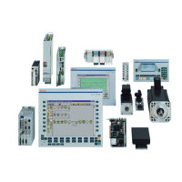
c) Determining the Drive Configuration Labelling
The following illustrations offer an idea on how to determine the
configuration labelling.
Illustration: Determining the Motor/Controller
Combination
Vmax
FdN Fmax
ED Controller Motor type
.........
Vmax
FdN Fmax
ED Controller Motor type
.........
Velocity/torque
need?
Constructive
requirements?
Determining the motor/controller combination
Selection list
Motor type
Fp5002d1.fh5
Fig. 5-3: Illustration for working with selection lists