Do you have a question about the REXROTH SYNAX200 and is the answer not in the manual?
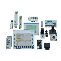
Overview of SYNAX200 system components including drives, motion control, and connections.
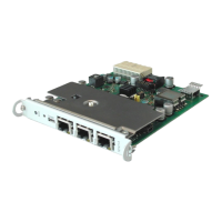
Introduces PPC-R units, basic devices, and available option modules.
Details motors, drive controllers, plug-in modules, and their configurations.
Guidance on the intended and correct usage of Rexroth Indramat products.
Defines the intended applications for SYNAX200 and what constitutes inappropriate use.
Explains warning symbols and degrees of hazard seriousness according to ANSI.
Lists specific dangers from incorrect use and precautions against electrical shock.
Provides general safety guidelines, personnel qualifications, and environmental conditions.
Details measures to prevent electrical shock from live parts and PELV.
Addresses hazards from movements, magnetic fields, hot parts, and handling.
Outlines safety for batteries and pressurized systems.
Introduces PPC-R units, enclosure versions, and provides installation dimensions.
Details installation instructions, arrangement, and slot addressing for module carriers.
Shows combination possibilities of module carriers with PPC and I/O modules.
Covers general specifications, power supply, I/O, EMC, and interfaces.
Illustrates connections for power, I/O, and details connector pin assignments.
Outlines the recommended procedure for determining drive configuration.
Details configurations for rotary axes with various position detection methods.
Explains linear axes configurations with indirect, direct incremental, and absolute position detection.
Describes parallel I/O cards (DEA04, DEA08) and their combination options.
Explains master axis encoder connections and emulation methods.
Details DGA 01.2 for encoder branching and signal output as square-wave signals.
Lists drive configurations based on basic configurations BE12, BE32, BE37, BE45, HS12, HS32, HS37, HS45.
Illustrates a SYNAX200 system configuration for a rotary press and folding machine.
Explains fibre-optic transmission ring structure, cable types, and planning notes.
Safety warnings for fibre-optic cables and guidelines for routing, mounting, and storage.
Instructions for setting drive addresses and checking distortion displays.
Procedures for checking and setting transmission rates and optic output power.
Overview of PPC link creation, ring types, and link address settings.
Steps for commissioning the PPC link and clearing associated errors.
Instructions for connecting the PPC to a PC using SynTop software via serial cable.
Details setting up RS485 links and bus matching for multiple PPC communication.
Dimensional sheets for module carriers RMB02.2-02 and RMB02.2-04.
Dimensional sheets for PPC-R01.2 and PPC-R02.2 units.
Terminal diagrams for Profibus, INTERBUS, and DeviceNet interfaces.
Details for RME02.2-16-DC024 and RME02.2-32-DC024 input modules.
Details for RMA02.2-16-DC024-200, RMA02.2-32-DC024-050, RMA02.2-16-AC230-200, RMA02.2-16-RE230-200 output modules.
Terminal diagrams for DAG, DSA, DEF, DFF encoder interfaces.
Lists connectors and ready-made cables with order designations and part numbers.
Lists related supplementary documentation for plug-in modules.
| Brand | REXROTH |
|---|---|
| Model | SYNAX200 |
| Category | Control Systems |
| Language | English |