6-8 Determining the Control-Related Plug-In Cards SYNAX200
DOK-SYNAX*-SY*-07VRS**-PR01-EN-P
6.6 Encoder Branching DGA 01.2 for Encoders with
Sinusoidal Voltage Signals 1Vss
General
X6 X5
X3 X4
X1 X2
Read and follow
Instructions for Electrical Drives"
manual,
DOK-GENERL-DRIVE******-SVS...
DANG
High oltage.
Danger of electrical shock.
Donot touch electrical connections
fo
5 minutes after switching
LWL
U1 (DSS)
U2 (DLF)
IKS4383
SY7PR107.FH7
external
incremental encoder
with sine output
e.g., Heidenhain
ROD 481
ERN 180
ERN 680
RON 285
e.g., external
register control
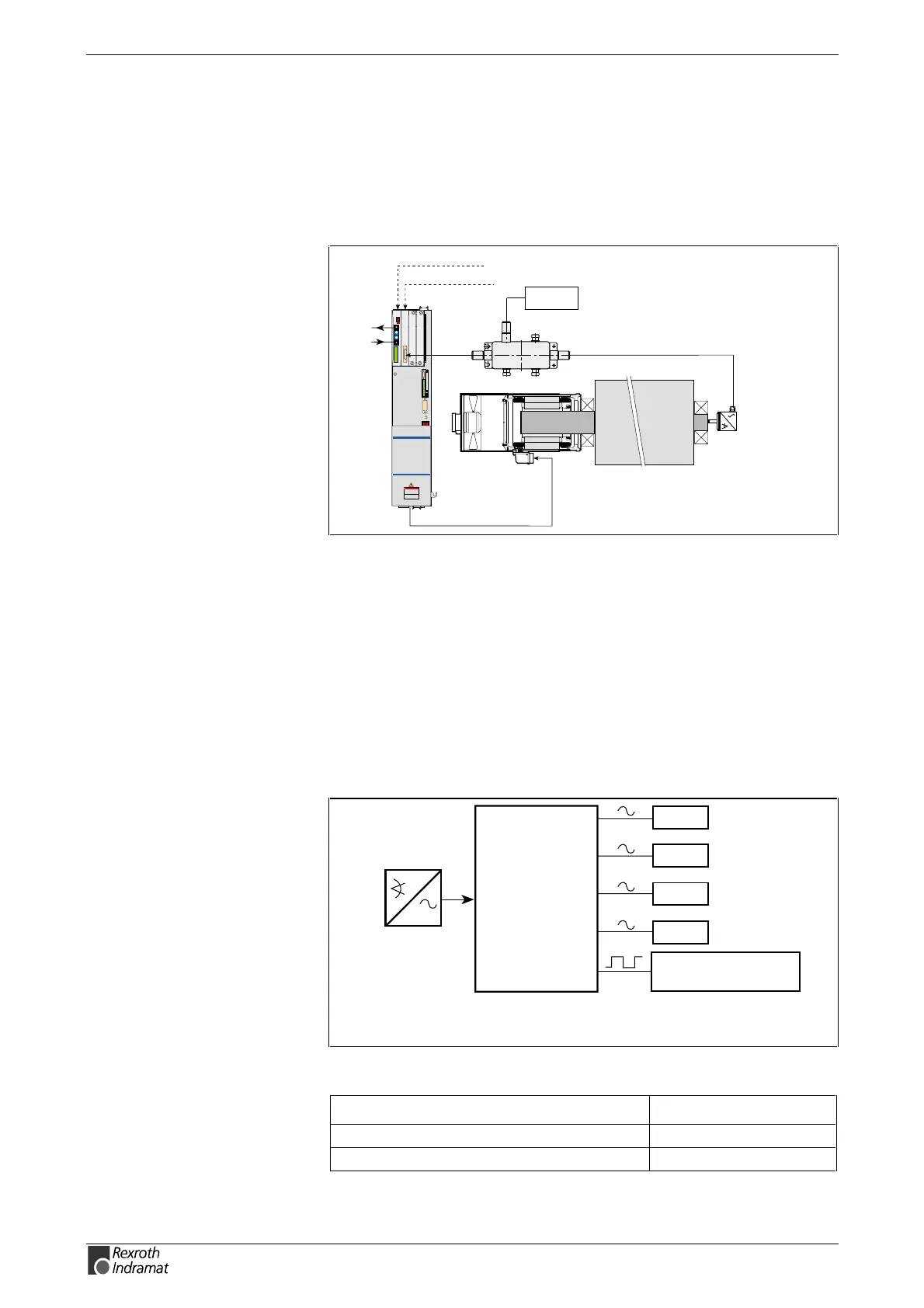
Fig. 6-14: Encoder branching DGA 01.2 example
The DGA makes it possible to distribute the signals of a measuring
system to up to four measuring system inputs of different drive
controllers. Possible applications of the DGA are:
• Parallel connection of linear motors using a measuring system
• Diverting position signals to external controls for the purpose of
monitoring or as master axis positions
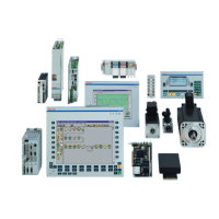
All measuring systems with sinusoidal output signals and a signal level of
1 V
SS
can be used (Heidenhain voltage interface).
The DGA makes it possible to connect up to four drive controllers. There
is also an output with square-wave signals.
Sv5115f1.fh7
1V
SS
DGA01.2
Measuring system:
Linear scale or
rotary encoder
Ext. control or meas.
signal evaluation
DLF01.1
DLF01.1
DLF01.1
DLF01.1
X1
X2
X3
X4
X5
X6
1)
1)
Terminal X2 supplies voltage for the
DGA and must always be present.
Fig. 6-15: Connection schematics - DGA01.2
Connection Ready-made cable
from DGA01.2 (X2, X3, X4, X5) to DLF01.1 IKS0131
from DGA01.2 (X6) to DEF01.1 IKS0331
Fig. 6-16: Ready-made cable
Connection schematics DGA01.2
Ready-made cable