SYNAX200 PPC Motion Control Configuration 4-5
DOK-SYNAX*-SY*-07VRS**-PR01-EN-P
4.3 Installation Instructions
The module carriers must first be installed before the PPC-R units can be
installed. These module carriers are equipped with the PPC-R unit and,
according to the requirements, with the related I/O modules (RECO02
modules).
Installing the module carriers
To install the RMB02.2-04 module carrier, you must latch it onto a DIN rail
TS 35x27x15 and secure it with a retaining screw. The module carrier
may also be installed directly on the installation plate in the control
cabinet. This is done through boreholes provided in the module carrier
(Fig. 4-5).
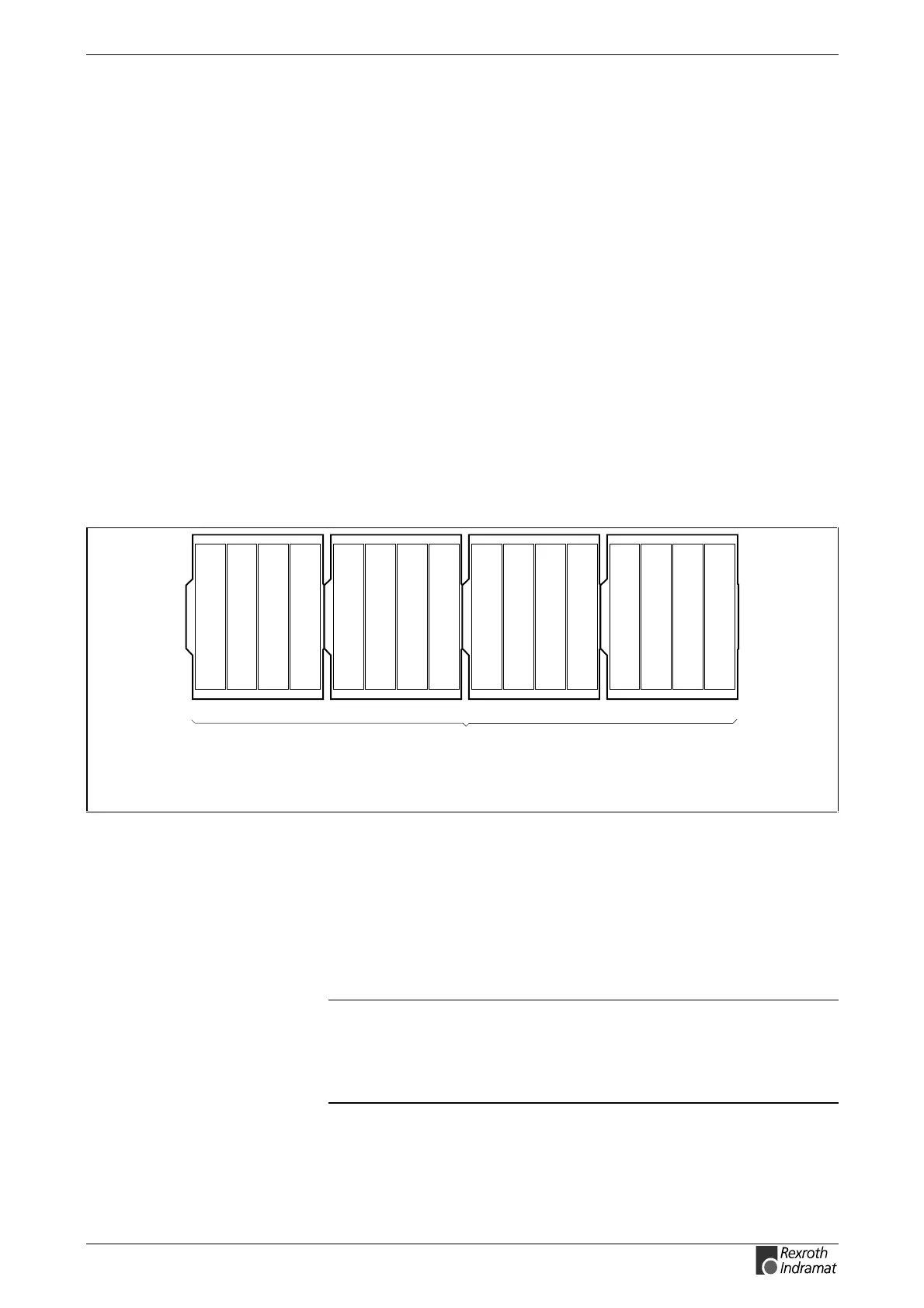
Up to four RMB02.2-04 module carriers can be installed side by side. The
PPC-R must be in slot 0 if it shall be able to control the RECO bus. Slot
addressing requires the DIP switches on the bus boards of the RMB02.2-
04 module carriers to be configured (Fig. 4-9). The dual carrier RMB02.2-
02 is used if the PCR-R shall be used on its own without RECO bus.
Arrangement of the module carriers
4x RMB02.2-04
with a total of 16 module slots for
accommodating PPC-R and up to 15
different I/O modules
RMB02.2-04_Anord.FH7
Fig. 4-7: Maximum configuration RMB02.2-04
Installing the modules
Starting with a PPC-R in slot 0 (left-hand side), the modules are plugged
into the RMB02.2-04 module carrier. Each module is secured with two
fixing screws. The I/O modules (RECO02.2) are added in the slots 1-15
or 2-15 (with PPC-R02.2) to the right-hand side of the PPC-R. You may
leave gaps to be able to install additional modules later.
Note: Prior to commissioning, you must tighten the fixing screws of
the module carriers in order to avoid lateral movements that
may lead to a disconnection of the connectors. (The location
of the screws is shown in Fig. 4-5). The modules must be
screwed to the module carrier.