4-12 PPC Motion Control Configuration SYNAX200
DOK-SYNAX*-SY*-07VRS**-PR01-EN-P
4.9 Connector Pin Assignments
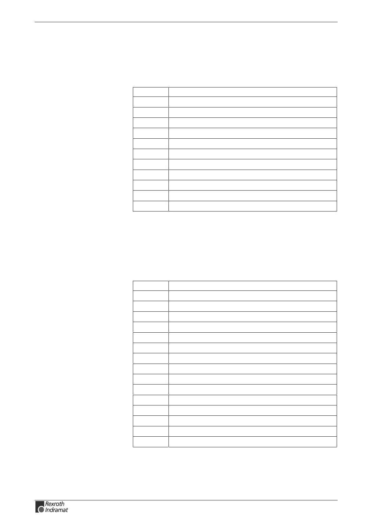
X1 (11-way Phoenix female connector)
Pin Signal name
1 Digital output 1 (Q1)
2 Digital output 2 (Q2)
3 Digital input 1 (I1)
4 Digital input 2 (I1)
5 Digital input 3 (I1)
6 24V external voltage
7 External GND
8Bb relay
9Bb relay
10 24V
11 GND
Fig. 4-18: Connector pin assignments X1
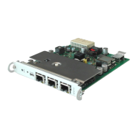
PROG / COM interface (X10, X16)
Serial interface to Indramat standard (SIS – 15-way DSUB female
connectors).
Both interfaces have full modem capability. The PROG interface is
isolated.
Pin Signal name
1 (Protected ground) NC
2 RS232 TxD
3 RS232 RxD
4 RS422 RxD+ or RS485+
5 RS422 RxD+ or RS485+
6DSR
7 Signal ground
8 DCD
9 RS232 TxD
10 GND
11 RS232 TxD
12 +5V
13 RTS
14 CTS
15 DTR
Fig. 4-19: Interface pin assignments of X10 and X16