11-26 Appendix SYNAX200
DOK-SYNAX*-SY*-07VRS**-PR01-EN-P
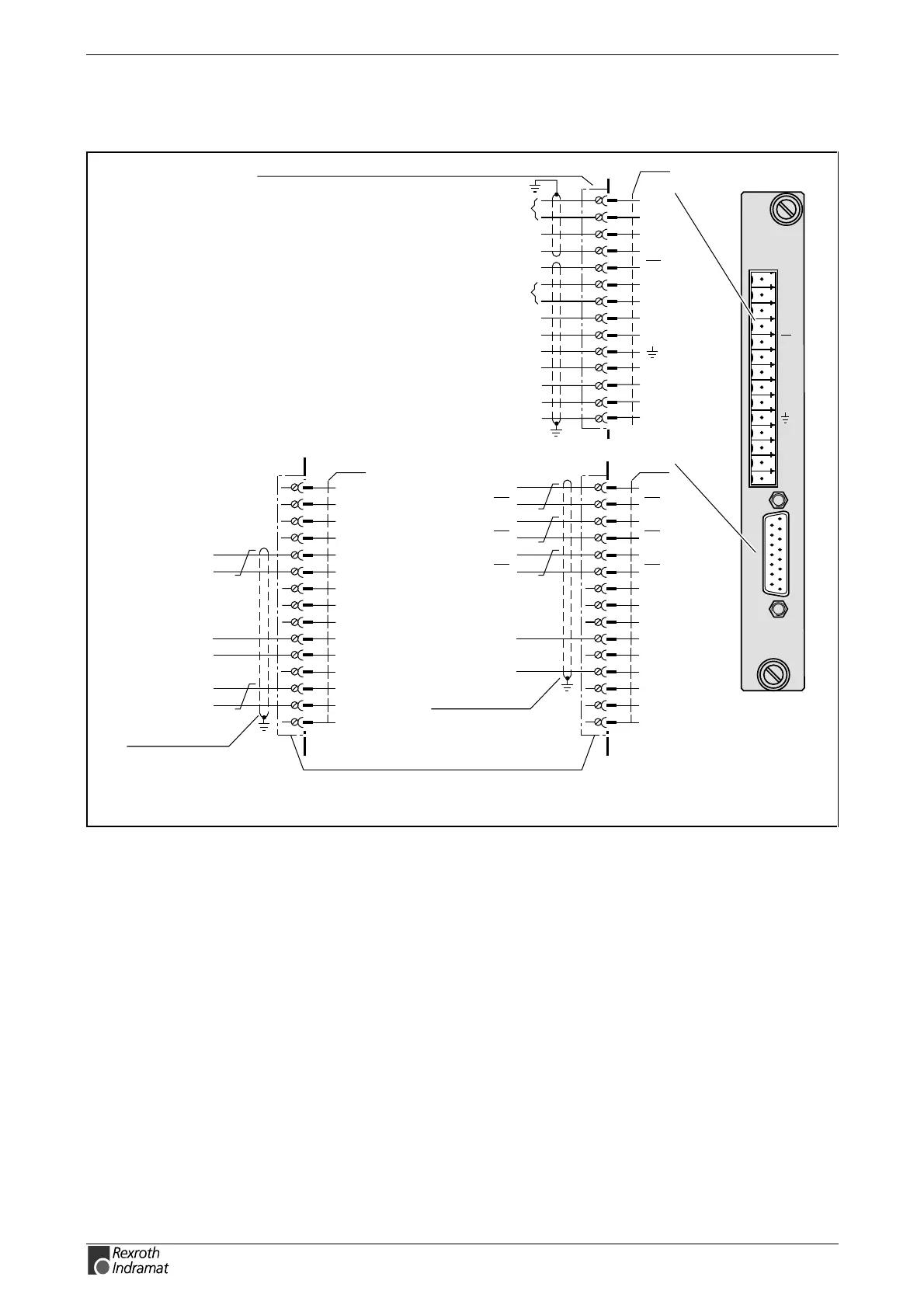
Analog interface with Actual Position Value Output DAE02.1M
E1+
E1-
TVW
RF
AH
E2+
E2-
+U
L
OV
L
CLR
STOP
FB+
FB-
12
SY6PR054.FH7
looking towards
front panel
14-pin plug-in, screw clamp, part no.: 274838
± 10V analog input 1
clear error
stop
pos. travel range limit switch
neg. travel range limit switch
DC +24V ext.
DC 0V ext.
8
1
3
4
5
6
7
2
9
10
U
a2
U
a2
U
a0
U
a0
U
a1
U
a1
free
free
free
0 V
+ 24 V
+5 V
free
free
free
DC 0 V ext.
DC +5 V ext.
X76
11
13
14
15
12
8
1
3
4
5
6
7
2
9
10
11
13
14
15
U
a2
U
a2
U
a0
U
a0
U
a1
U
a1
GY
PK
RD
BK
BN
GN
WH 1
2
BN 1
2
15-pin D-SUB connector INS0519/L01
(screwed mounting) part no.: 263365
incremental encoder emulator
12
8
1
3
4
5
6
7
2
9
10
free
free
free
free
data (+)
data (–)
free
free
free
0V
+24 V
+5 V
pulse (+)
pulse (–)
free
DC 0 V ext.
DC +24 V ext.
11
13
14
15
12
8
1
3
4
5
6
7
2
9
10
11
13
14
15
BN
GN
BN 1
2
WH 1
2
absolute encoder emulator
(SSI data format)
X76
BK
RD
pulse (+)
pulse (–)
DATA (+)
DATA (–)
1)
color coding applies to INDRAMAT cable type INK 0209
1)
1)
cable (2x1,0 +
4x2x0,25)C
type INK 0209
cable (2x1,0 +
4x2x0,25)C
type INK 209
drive enable
drive halt
temperature prewarning
± 10V analog input 2
1
2
3
4
5
6
7
8
9
10
11
12
13
14
X75
E1+
E1-
TVW
RF
AH
E2+
E2-
+U
L
0V
L
CLR
STOP
FB+
FB-
DAE02.1
M
X76
X75
Fig. 11-28: Terminal diagram DAE02.1M