SYNAX200 Determining the Control-Related Plug-In Cards 6-11
DOK-SYNAX*-SY*-07VRS**-PR01-EN-P
Diverting Measuring System Signals to Four Connection
The signals from the measuring system are diverted to connections X2,
X3, X4 and X5.
The DGA01.2 receives ist power via terminal X2.
Connecting voltage X2/3: DC +8 V (
±5%)
Maximum current consumption: 300 mA
see Fig. 6-18: Signal input circuit
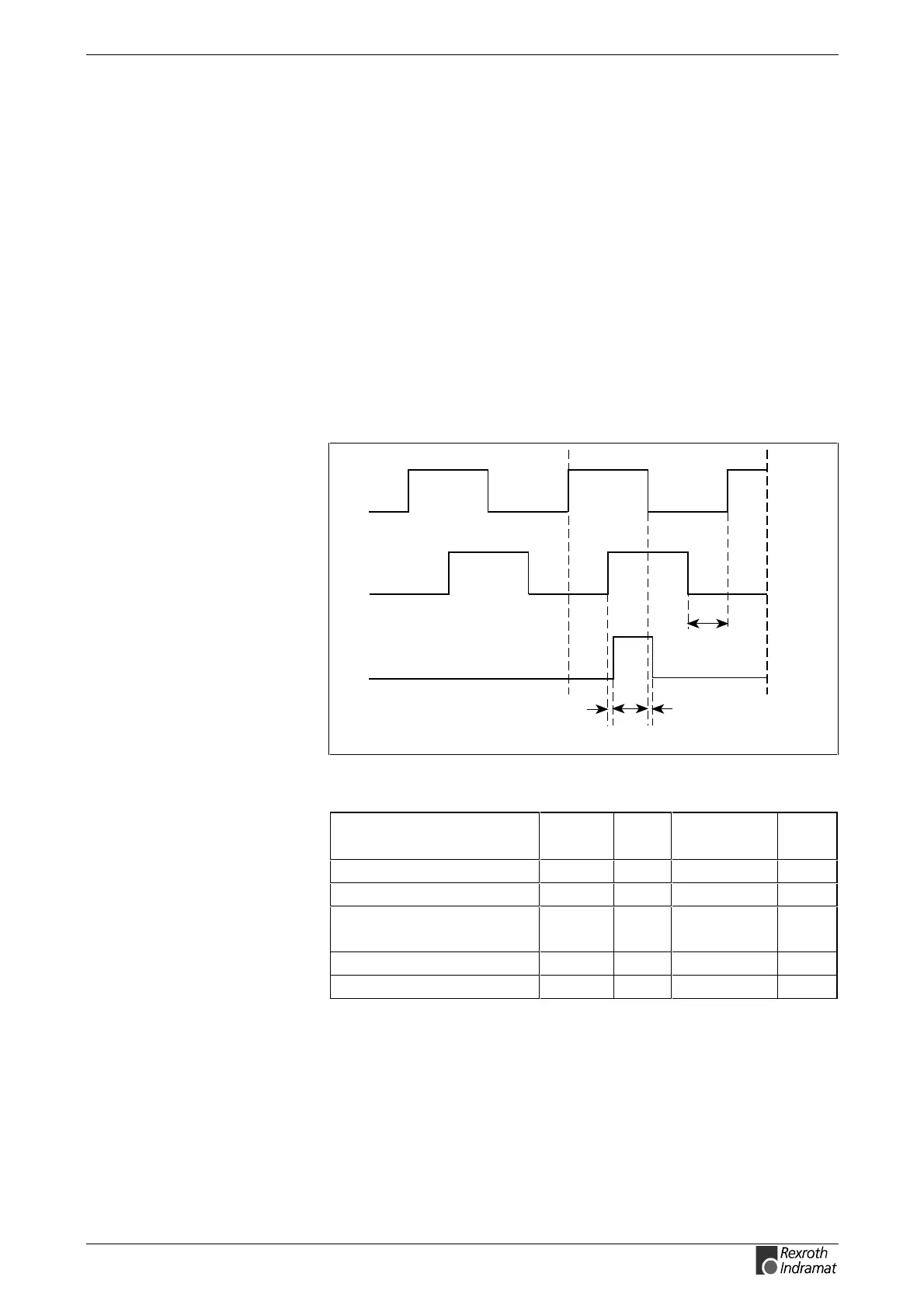
Outputting Measuring System Signals as Square-Wave
Signals
Sinusoidal signals of the measuring system are generated via terminal X6
as square-wave incremental signals.
t2
t1
Ua1
Ua0
Ua2
Sv5117f1.fh7
Encoder shaft turning clockwise
t1
Fig. 6-20: Voltage level and phase position of incremental signals
Designation Unit min. type /
value
max.
Phase position Ua1 degree 0
Phase position Ua2 degree 90
Signal amplitude
Ua-(/Ua)
V
SS
7
Reference point delay t1 ns 50
Edge distance t2 ns 500
Fig. 6-21: Incremental signal data
DGA01.2 supply
Recommended signal input
circuit