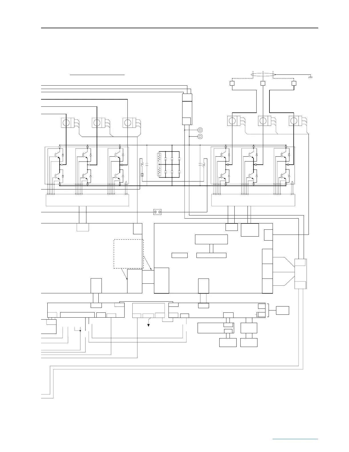
Frame 2 Schematic B-5
PowerFlex® 700L Liquid-Cooled Drive User Manual
Publication 20L-UM001D-EN-P
700L Fr2 - Contactor K2 RA# 100-d420ed11
Contactors
Contactor K1 RA# 100-c60d10
CT1
-
M
+
CT2
-
M
+
CT2
-
M
+
CT4
-
M
+
CT5
-
M
+
CT6
-
M
+
RS
T
WV
U
CT Part # LEM: HAL 600-S
CT Part # LEM: HAL 600-S
Each Cap (C6-C11) = 9,000 µF
Cap Total = 13,500 µF
Converter
Module
Direct Liquid
Cooled Power
Module
Inverter
Module
Direct Liquid
Cooled Power
Module
GATE DRIVER PCB
CONVERTER
IGBT GATE DRIVER PCB
INVERTER
NTC NTC
R7 - 15K
R8 - 15K
Conv.
Snubber
Te mp
Switch
0.4 µF
Conv.
Snubber
C6 C7 C8
C9 C10 C11
-DC
+DC
DC- Test Point
DC+ Test Point
0.4 µF
Inverter
Snubber
Inverter
Snubber
Te mp
Switch
C5C4
J7
J12
LEM
J1
40-pin
Gate
Drive
CONVERTER POWER
INTERFACE PCB
For Inv/Conv Drive
This is a power
Feed for the Conv
POWER INTERFACE
PCB
Power
Jumper to
2nd Power
Interface
PCB
Also carries the
Inverter Gate Enable
J6
TB1(1a - 12)
TB1(1a - 10)
20-Pin
J8
20-Pin
Aux
Out
NO
Aux
Out
Com
Aux
In
24V
SOC
In+
Aux
In
SOC
In-
Safety
HW
En
J4
J1 J9
40-Pin
10-Pin 10-Pin
30-Pin
9-Pin
700S Ph II Option: SOC Signal
Vector Option: SOC Signal
700S Ph II Only
Additional
Options
700S Ph II
Encoder PCB
(Vector Option)
Control
and I/O
Power and
Signal
I/O and
Network
Note:
P1, P2, P6 connectors on PF700S Ph II control board.
J2, J3, J7 connectors on PF700 Vector control board.
CONVERTER
CONTROL PCB
9
Unused
10 13
14 15 7
8
P1
Power
Jumper to
2nd Power
Interface
PCB
J8
J1
40-pin
J11
J10
Voltage Feedback PCB
(PF 700S Ph. II Only)
Vector Option: Jumper between 9 & 10
700S Ph II Option: Voltage Feedback Board
INVERTER POWER INTERFACE PCB
TB1(1b - 4)
J9
J7
700S Ph II
Option: From
Gate Drive
Gate
Drive
J6
SMPS
Con
J1
J5
SMPS
Con
J2
J4
SMPS
Con
J3
J12
LEM
9-Pin
COMM
Option
20-Pin
30-Pin
30-Pin
T-Board Comm Interface
P6
TB2
J3/P2
J2/P1
SOC
In+
SOC
In-
21
40-Pin
INV. CONTROL PCB
See Catalog String
J7
TB1
TB2
20-pin
J5
J1
20-pin
80 W
SMPS
PCB
(A05)
J3
J4
41
Ps+
+300Vdc
-300Vdc
Ps-
J1
80 W
SMPS
PCB
(A07)
876
J3
41
UVW
Three Phase A.C. Output
Motor Shield
TB1(1b - 15)
 Loading...


