Frame 3A and 3B Schematics C-3
PowerFlex® 700L Liquid-Cooled Drive User Manual
Publication 20L-UM001D-EN-P
V
U
W
1
P2
7
4
L1301
302
303
L3
L2
J1
J1
J8
J4
J9
J8
P1
P6
TB2
Aux_Out_NO
Aux_Out_COM
Aux_In_24V
Safety_HW_EN
-
9
10
SOC_In+
SOC_In-
SOC_In+
SOC_In-
7
8
3
4
1
2
311
320
14
13
Factory-Installed Jumper
-
-
1
2
RED
RED
3
4
6
7
5
GRN
RED
9
8
11
10
WHT
+24VDC
120 VAC Line
Precharge Coil
Gate Enable
Precharge Feedback
Inductor Overtemp
2
1
6
5
4
314
313
312
315
7
316
Factory-Installed Jumper
For additional detail, see Power Module schematic.
L2 L1L3
BLU
BLU
BLU
TB5
TB2
POWER MODULE BAY
120 VAC Neutral3
310
WHT
N
318
L1
300
PE
317
M6
Power Module
Bay Door
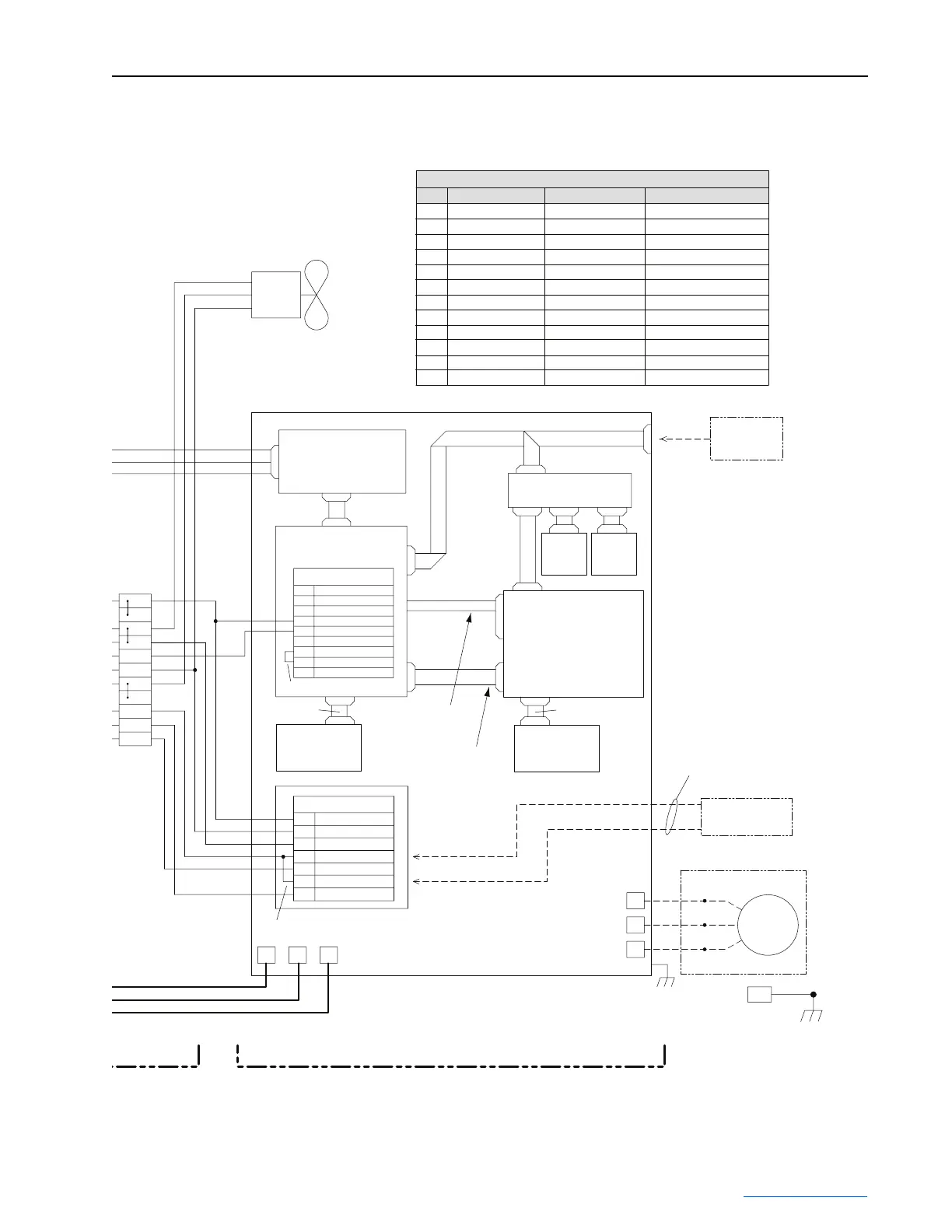
NOTES:
1.) Dashed lines indicate external components and wiring by others.
FUSE TABLE - DRIVE INPUT
Class CC, 1A/600VFU7
FU11
FU12
FU10
FU9
FU8
Class CC, 20A/600V
Class CC, 20A/600V
Class CC, 1A/600V
Class CC, 1A/600V
Class CC, 20A/600V
FU5
FU6
FU4
FU1
FU2
FU3
Ref.
Class CC, 10A/600V
Class RK-5, 5A/600V
Class RK-5, 5A/600V
150A/600V
150A/600V
150A/600V
Fuse Description Supplier "A" and P/N Supplier "B" and P/N
Bussman FRS-R-5
Bussman FRS-R-5
Bussman FWH-1508
Bussman FWH-1508
Bussman FWH-1508
Littelfuse KLDR010
Littelfuse CCMR020
Littelfuse CCMR020
Littelfuse CCMR020
Littelfuse KLDR001
Littelfuse KLDR001
Littelfuse KLDR001
Ferraz Shawmut TRS5R
Ferraz Shawmut TRS5R
Ferraz Shawmut A50P150-4
Ferraz Shawmut A50P150-4
Ferraz Shawmut A50P150-4
Ferraz Shawmut ATQR10
Ferraz Shawmut ATDR20
Ferraz Shawmut ATDR20
Ferraz Shawmut ATDR20
Ferraz Shawmut ATQR1
Ferraz Shawmut ATQR1
Ferraz Shawmut ATQR1
Voltage Feedback
Resistor PCB
Active Converter
Control PCB
IGBT Converter / IGBT Inverter
Power Module
COMM
PCB
(Option)
Cassette
HIM
(Option)
Communication I/F PCB
DPI Signal
Main Control PCB
Addressable
Power PCB
J3 - PF 700 Vector Only
P2 - PF 700S Phase II Only
J2 - PF 700 Vector Only
P1 - PF 700S Phase II Only
SOC Signal
PF 700 Vector Only
SOC Signal
PF 700S Phase II Only
40-Pin Ribbon
30-Pin Ribbon
Door-Mounted
HIM
(Option)
Replaces Factory-Installed
Jumper on TB5-4 and TB5-6
Stop Circuit
Connection
External
GRD
T1/T6
T3/T5
T2/T4
M5
Motor
J8
Addressable
Power PCB
40-Pin Ribbon
PM
 Loading...


