Frame 3A and 3B Schematics C-13
PowerFlex® 700L Liquid-Cooled Drive User Manual
Publication 20L-UM001D-EN-P
222A
10
TB2
8
9
7
6
5
4
3
2
1
11
GRN
WHT
POWER MODULE BAY
310
316
315
314
313
312
320
311
303
301
302
BLU
BLU
BLU
317
300
318
M6
L1
PE
N
WHT
RED
GRN
WHT
RED
RED
Power Module
Bay Door
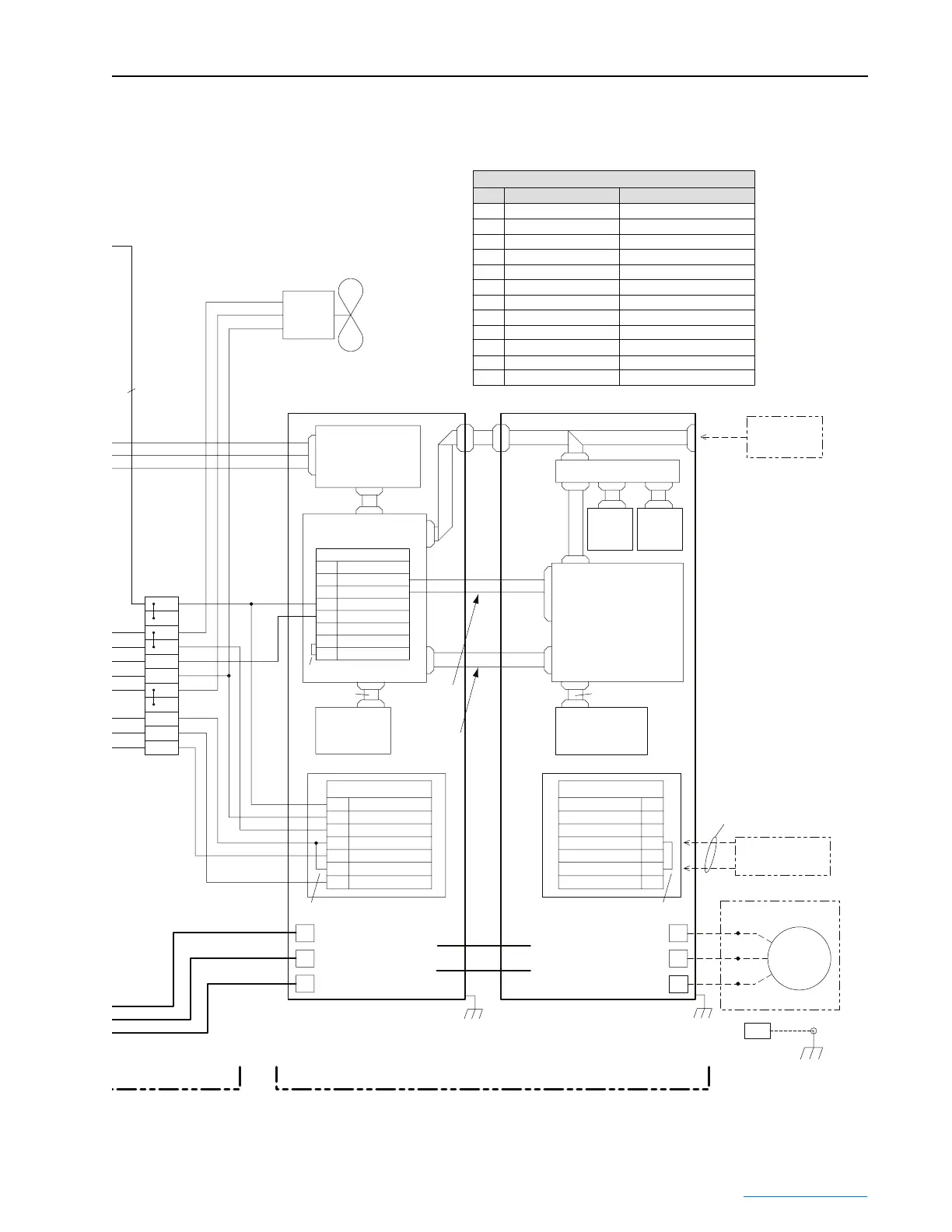
NOTES:
1.) Dashed lines indicate external components and wiring by others.
FUSE TABLE - INPUT FILTER BAY
Euro/IEC gl-gG 1A/690VFU7
FU11
FU12
FU10
FU9
FU8
Euro/IEC gl-gG 20A/690V
Euro/IEC gl-gG 20A/690V
Euro/IEC gl-gG 1A/690V
Euro/IEC gl-gG 1A/690V
Euro/IEC gl-gG 20A/690V
FU5
FU6
FU4
FU1
FU2
FU3
Ref.
Class CC, 10A/600V
Euro/IEC gl-gG 6A/690V
Euro/IEC gl-gG 6A/690V
Style QS, 300A/700V
Style QS, 300A/700V
Style QS, 300A/700V
Fuse Description Supplier and P/N
Ferraz Shawmut 18023-G
Ferraz Shawmut 18023-G
Ferraz Shawmut A70QS300-4
Ferraz Shawmut A70QS300-4
Ferraz Shawmut A70QS300-4
Ferraz Shawmut ATQR10
Ferraz Shawmut 17037-G
Ferraz Shawmut 17037-G
Ferraz Shawmut 17037-G
Ferraz Shawmut 17011-G
Ferraz Shawmut 17011-G
Ferraz Shawmut 17011-G
L2
L1
L3
7
6
4
5
3
1
2
14
13
-
10
9
8
7
4
3
2
1
-
120 VAC Neutral
Inductor Overtemp
Precharge Feedback
Gate Enable
+24VDC
Precharge Coil
120 VAC Line
7
6
4
5
3
1
2
Gate Enable
+24VDC
TB5
Safety_HW_EN
Aux_In_24V
Aux_Out_COM
Aux_Out_NO
SOC_IN_
SOC_IN+
SOC_IN_
SOC_IN+
V
U
Replaces Factory-Installed
Jumper on TB6-4 and TB6-6
W
J8
J4
J9
P6
J8
J1
J1
L3
P2
P1
7
4
L1
L2
1
DC BUS
-
+
DC BUS
-
+
Voltage Feedback
Resistor PCB
Active Converter
Control PCB
Addressable
Power PCB
Factory-Installed Jumper
For additional details, see Power Module schematic.
TB6
Factory-Installed Jumper
Factory-Installed Jumper
40-Pin Ribbon
SOC Signal
PF 700 Vector
Only
SOC Signal
PF 700S Ph. II
Only
PMC
IGBT Converter Power Module
PMI
IGBT Inverter Power Module
Door-Mounted
HIM
(Option)
Stop Circuit
Connection
GRD
External
T3/T5
T2/T4
T1/T6
M5
Motor
J3 - PF 700 Vector Only
P2 - PF 700S Phase II Only
J2 - PF 700 Vector Only
P1 - PF 700S Phase II Only
COMM
PCB
(Option)
Cassette
HIM
(Option)
30-Pin Ribbon
Communication I/F PCB
DPI Signal
TB2
Main Control PCB
J8
Addressable
Power PCB
40-Pin Ribbon
 Loading...


