Frame 3A and 3B Schematics C-17
PowerFlex® 700L Liquid-Cooled Drive User Manual
Publication 20L-UM001D-EN-P
R
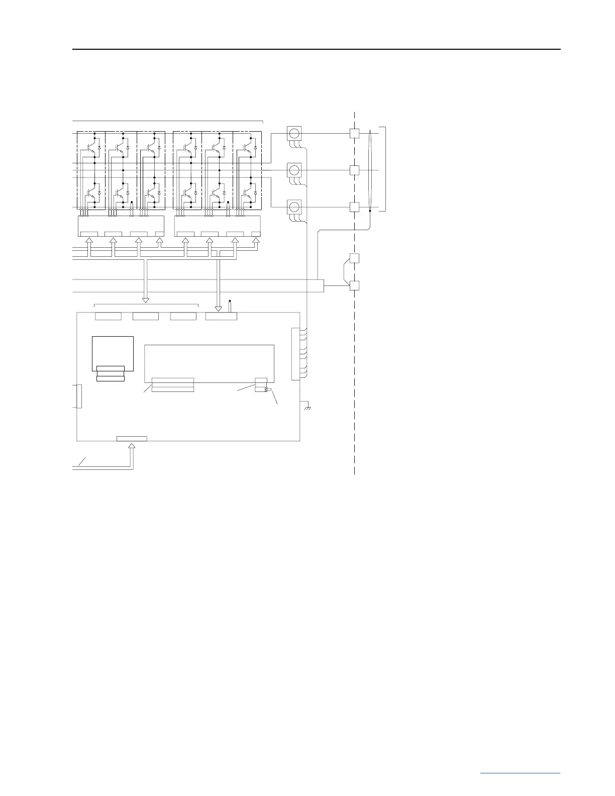
Current
Feedback
J7
PE
Earth Ground
CT1
CT2
CT3
U
V
W
Three Phase
A.C. Output
Motor Shield
Inverter IGBT Modules Option
IGBT Interface PCB IGBT Interface PCB
W Gate
J6
V Gate
J5
U Gate
J4
NTC
J1
J1 J2 J3 J4 J1 J2 J3 J4
40-Pin
Shielded Cable
Chillplate NTC
J8
Jumper J3-9, 10
if option not used.
See Note 3.
J2
J3
Voltage Feedback PCB
(PF 700S Ph. II Only)
P3 P2
J9
PE
Motor Ground
28-Pin
Board-to-Board
16-Pin
Board-to-Board
Addressable Power PCB
#3 - Upper Middle #4 - Top
N
T
C
N
T
C
NOTES:
1.) MOV's must be installed in the input filter section of the drive.
2.) Corner grounding is:
A. Permitted for 400V, 480V, and 600V Classes.
B. Not permitted for 690V Class.
3.) Jumper J3-9, 10 is provided with the Addressable Power PCB.
4.) SOC cable and DPI cable are used only with Inverter Power
Modules coupled to Converter Power Modules. These cables
are not used with stand-alone Inverter Modules.
5.) Product software supports only one external HIM. Do not connect
external HIM if one is also connected to the Converter Power Module.
A splitter box is required for multiple external HIM devices.
J11
J5
Inverter
Rating Plug
PCB Option
 Loading...


