Frame 3A and 3B Installation 3-9
PowerFlex® 700L Liquid-Cooled Drive User Manual
Publication 20L-UM001D-EN-P
complete drive equipment at its installation site, remove both the pallet and
the pallet mounting brackets. For safety when removing the pallet mounting
brackets, place blocks under the hoisted cabinet (Figure 3.9
). The blocks
provide a measure of safety while the six (6) M12 screws are unfastened
under the cabinet to remove the pallet mounting brackets. After the
complete drive equipment is placed at its installation position, remove the
lifting angles to permit the installation of the vented top cover over the input
filter bay. Assembly instructions are provided with the vented top cover. If
the complete drive equipment must be moved for any reason, remove the
vented top cover and then reinstall the lifting angles to hoist the cabinet.
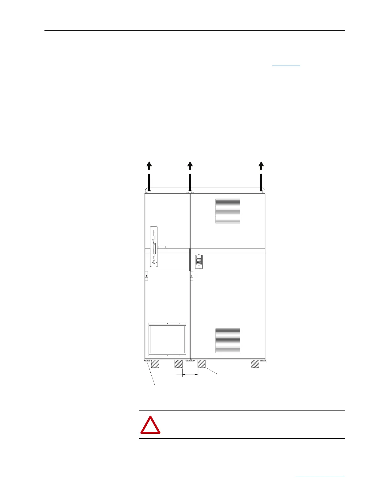
Figure 3.8 Frame 3 Complete Drive Lifting Instructions
Drive lifting points: three front (shown), and three back (not shown).
Pallet mounting brackets: three front (shown), and three back (not shown).
203
(8.00)
Maximum
Dimensions are in
millimeters and (inches).
Blocks for safe removal of pallet mounting brackets.
Full depth of cabinet. (4) - Places
!
ATTENTION: To guard against possible personal injury and/or
equipment damage, block the cabinet while removing the pallet
mounting brackets.
 Loading...


