3-26 Frame 3A and 3B Installation
PowerFlex® 700L Liquid-Cooled Drive User Manual
Publication 20L-UM001D-EN-P
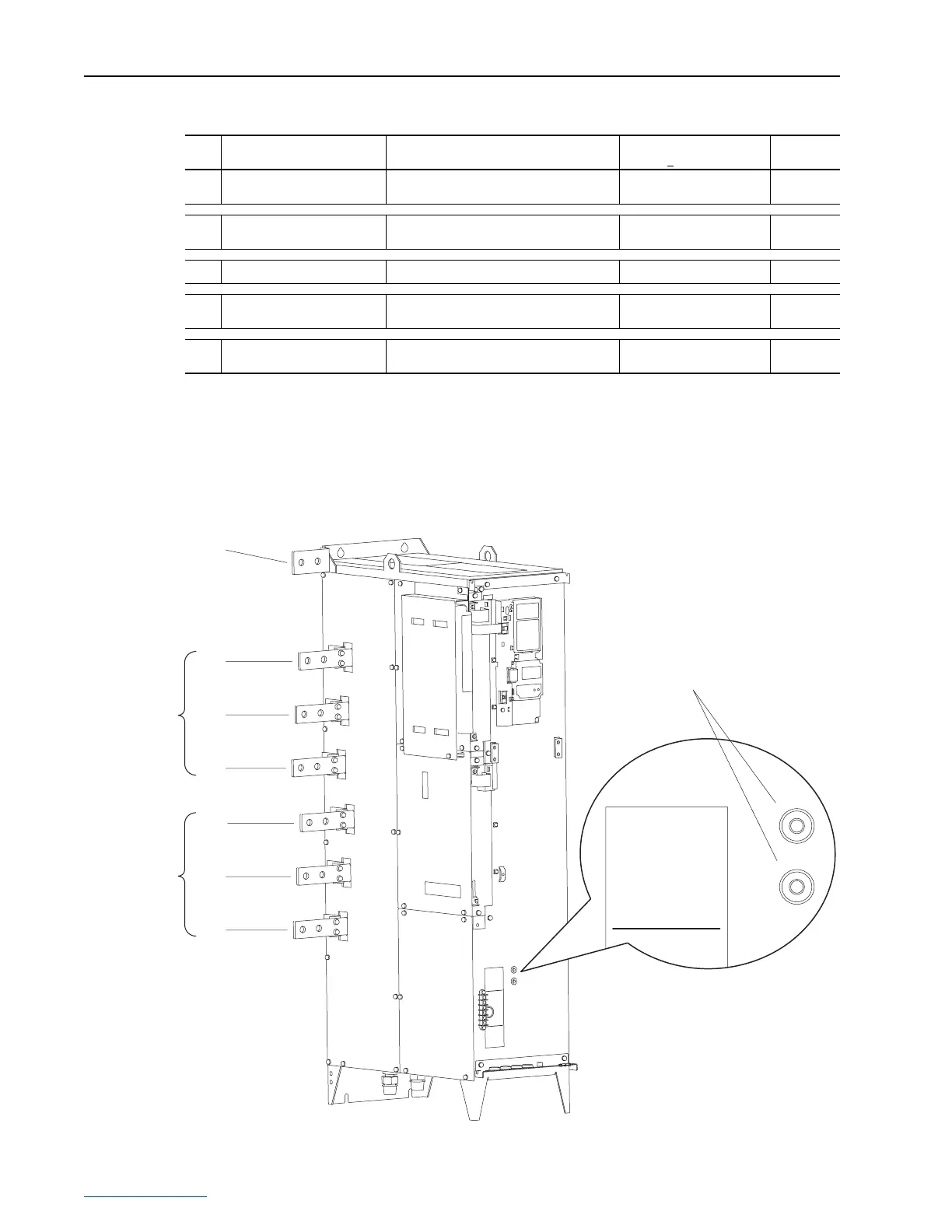
Table 3.C Power Module Terminal Specifications
Figure 3.25 Frame 3A Converter/Inverter Power Module Terminal Locations
Item Name Description
Recommended Tightening
Torque (+
10%)
Terminal
Bolt Size
(1)
➊
Input Power Bus Bar
(2)
R/L1, S/L2, T/L3
Input power 62 N•m (550 lb•in) M12
➋
Output Power Bus Bar
(2)
U/T1, V/T2, W/T3
Motor connections 62 N•m (550 lb•in) M12
➌
PE, Motor Ground Bus Bar
(2)
Terminating point for wiring shields 11 N•m (100 lb•in) M8
➍
DC Bus Test Point Socket
(3)
(2 Terminals; DC+, DC-)
4 mm socket for DC bus voltage
measurement only
——
➎
DC Power Bus Bar
(2)
(4)
(2 Terminals; DC+, DC-)
DC power from Converter Power Module to
Inverter Power Module (Frame 3B only)
62 N•m (550 lb•in) M12
(1)
Apply counter torque to the nut on the other side of terminations when tightening or loosening the terminal bolt to avoid damage to the terminal.
(2)
These connections are bus bar type terminations and require the use of lug connectors.
(3)
Use only to verify that DC bus capacitors are discharged before servicing the Power Module. No other external use is permitted.
(4)
Size DC power conductors for current carrying capacity as follows: 400/480V, 1000 Amps; 600/690V, 800 Amps.
W/T3
V/T2
U/T1
➋
T/L3
S/L2
R/L1
➊
➌
➍
DC+ TESTPOINT
DC- TESTPOINT
 Loading...


