Reference Manual
00809Rev BA-0100-4026, Rev FA
July 2009
Rosemount 5400 Series
www.rosemount.com
Section 2 Transmitter Overview
Theory of Operation . . . . . . . . . . . . . . . . . . . . . . . . . . . . . . page 2-1
Application Examples . . . . . . . . . . . . . . . . . . . . . . . . . . . . page 2-2
Components of the Transmitter . . . . . . . . . . . . . . . . . . . . page 2-4
System Architecture . . . . . . . . . . . . . . . . . . . . . . . . . . . . . . page 2-5
Process Characteristics . . . . . . . . . . . . . . . . . . . . . . . . . . . page 2-6
Antenna Selection Guide/Measuring Range . . . . . . . . . . page 2-7
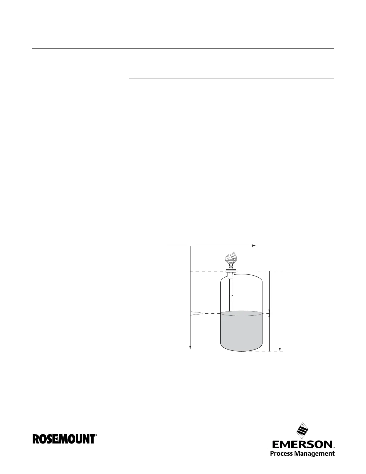
THEORY OF OPERATION The Rosemount 5400 Series Radar Transmitter is a smart, two-wire
continuous level transmitter. A 5400 transmitter is installed at the top of the
tank and emits short microwave pulses towards the product surface in the
tank. When a pulse reaches the surface, part of the energy is reflected back to
the antenna for subsequent processing by the transmitter electronics. The
time difference between the transmitted and reflected pulse is detected by a
micro-processor and is converted into a distance, which calculates the level.
The product level is related to the tank height and the measured distance by
the following expression:
Level = Tank Height - Distance.
Figure 2-1. Measurement
principle for the Rosemount
5400 Series.
Time
Level
Distance
Tank Height