Reference Manual
00809-0100-4026, Rev FA
July 2009
5-3
Rosemount 5400 Series
BASIC CONFIGURATION
PARAMETERS
This chapter describes the basic parameters that need to be configured for a
Rosemount 5400 transmitter. If the transmitter is factory-configured according
to the ordering specifications in the Configuration Data Sheet, no further basic
configuration is needed unless conditions have changed since the ordering
date.
Different configuration tools are described at the end of this section.
Measurement Units Measurement units can be specified for presentation of Level, Level Rate,
Volume and Temperature values.
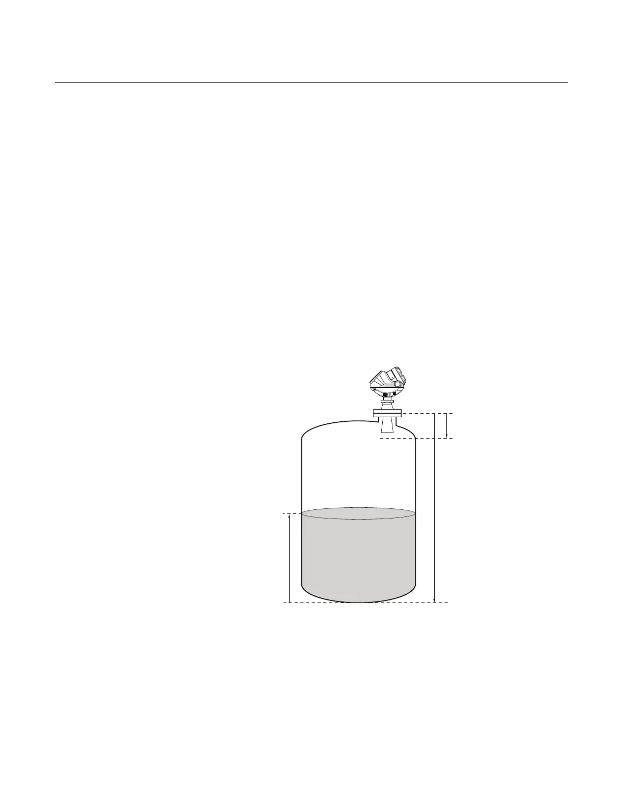
Tank Geometry Tank Height
The Tank Height is the distance between the Upper Reference Point at the
underside of the transmitter flange or the threaded adapter, and the Lower
Reference Point close to or at the bottom of the tank (see Figure 5-2 for
further information on Upper Reference Points for various tank connections).
The transmitter measures the distance to the product surface and subtracts
this value from the Tank Height to determine the product level.
Figure 5-1. Tank Geometry.
Tank Height (R)
Product Level
Upper Reference Point
Lower Reference Point
(Level=0)
Transition Zone