Reference Manual
00809-0100-4026, Rev FA
July 2009
Rosemount 5400 Series
www.rosemount.com
Appendix C Advanced Configuration
Tank Geometry . . . . . . . . . . . . . . . . . . . . . . . . . . . . . . . . . . page C-1
Advanced Analog Output Settings . . . . . . . . . . . . . . . . . . page C-3
Advanced Transmitter Settings . . . . . . . . . . . . . . . . . . . . . page C-4
Advanced Functions in RRM . . . . . . . . . . . . . . . . . . . . . . . page C-7
The advanced transmitter configuration includes settings which can be used
to fine tune the transmitter for special applications. Normally, the standard
settings are sufficient.
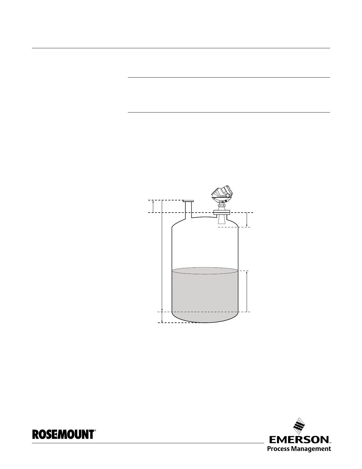
TANK GEOMETRY
Figure C-1. Advanced Tank Geometry
Distance Offset (G) The Distance Offset is used when hand-dipping is done at a separate nozzle.
By setting the Distance Offset the measured level by the gauge can be
adjusted to correspond with the level value obtained by hand-dipping.
Tank Height (R)
Product Level
Tank Reference Point
Distance Offset (G)
Min LevelOffset (C)
Upper Reference Point
Hold Off Distance
Lower Reference Point
(Level=0)