Reference Manual
00809-0100-4026, Rev FA
July 2009
5-21
Rosemount 5400 Series
CONFIGURATION USING
A 375 FIELD
COMMUNICATOR
This section describes the configuration of a 5400 transmitter with a 375 Field
Communicator.
The menu tree with the various configuration parameters is shown in Figure
5-11 on page 5-22.
Section “Basic Configuration Parameters” on page 5-3 describes the basic
configuration parameters. See sections “Echo Tuning” on page 5-10 and
“Advanced Configuration” on page C-1 for information on disturbance echo
handling and advanced configuration.
For information on all capabilities, refer to 375 Field Communicator Product
Manual (Document No. 00809-0100-4276).
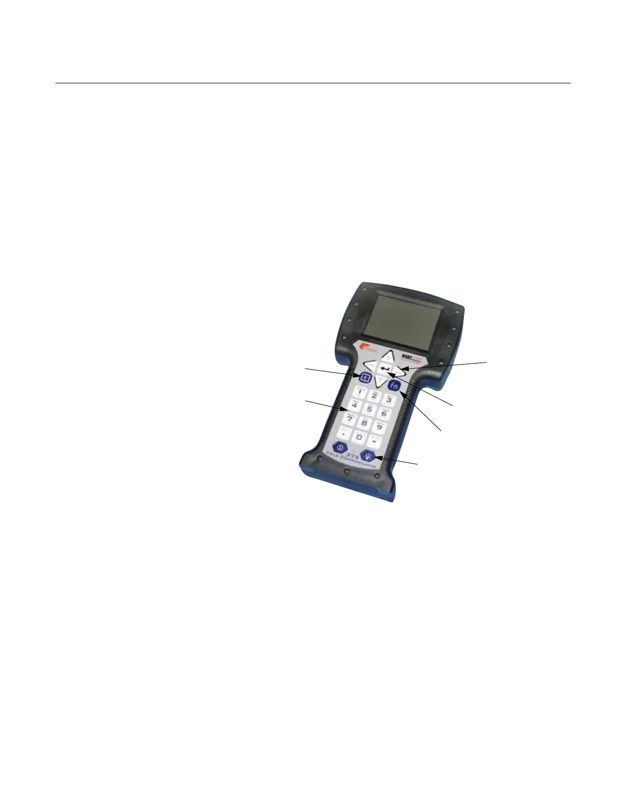
Figure 5-10. The 375 Field
Communicator.
To make a basic setup of the transmitter, do the following:
1. Check that the desired Measurement Units are selected. HART
command: [2, 1, 1, 5].
2. Enter configuration parameters for the following:
• Device info. HART command: [2, 2, 1]
• Geometry. HART command: [2, 1, 2]
• Environment. HART command: [2, 1, 3]
• Volume. HART command: [2, 1, 4]
• Analog Out. HART command: [2, 1, 5]
3. Run Measure and Learn. HART command: [2, 1, 6, 2]. This function
creates an Amplitude Threshold Curve (ATC).
4. Restart the transmitter. HART command: [2, 1, 6, 4].
To view the Echo Curve and adjust threshold settings, see “Using the Echo
Curve Analyzer with a 375 Field Communicator” on page 7-12.
Function Key
Navigation Keys
Alphanumeric Keys
Backlight adjustment key
Tab Key
Enter Key