Reference Manual
00809-0100-4026, Rev FA
July 2009
Rosemount 5400 Series
4-10
Configure Channels 1, 2, and 3 to reflect the units in addition to Upper Range
Values and Lower Range Values for secondary, tertiary, and fourth variables
(variable assignment is configured in the Model 5400). It is also possible to
enable or disable a channel from this menu.
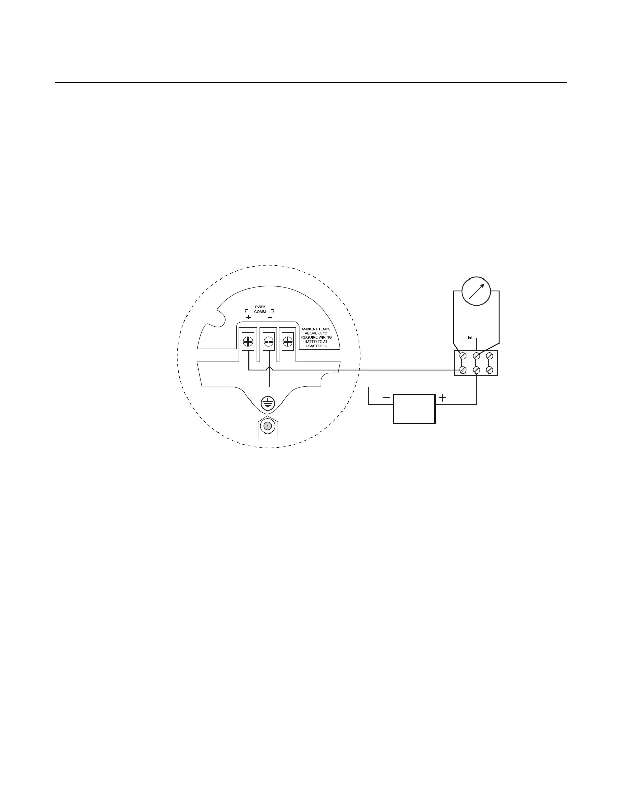
751 Field Signal Indicator
Figure 4-10. Wiring diagram for
a Rosemount 5400 transmitter
with a 751 Field Signal Indicator.
Power supply
Rosemount 5400
Radar Transmitter
Model 751 Field
Signal Indicator