Reference Manual
00809-0100-4026, Rev FA
July 2009
Rosemount 5400 Series
4-8
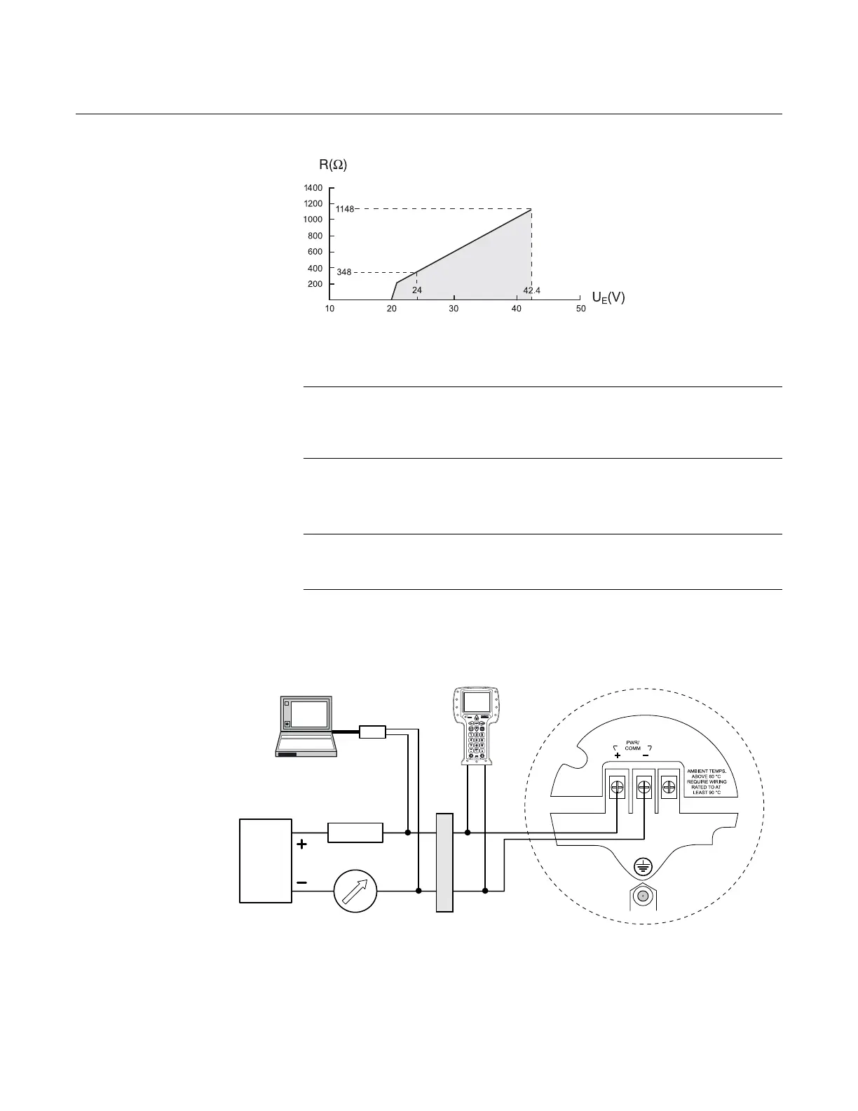
Figure 4-6. Maximum load
resistance for Explosion-Proof/
Flameproof installation.
See Figure 4-7 for wiring information.
NOTE!
For Explosion-proof/Flameproof installations make sure the transmitter is
grounded to the I.S. ground terminal inside the terminal compartment in
accordance with national and local electrical codes.
INTRINSICALLY SAFE
POWER SUPPLY
With an intrinsically safe power supply, wire the transmitter as shown in
Figure 4-7.
NOTE!
Make sure the instruments in the loop are installed according to intrinsically
safe field wiring practices.
Figure 4-7. Wiring diagram for
intrinsically safe power supply.
The 375 Field Communicator and the HART Modem require a minimum load
resistance within the loop of 250 to function properly. For maximum load
resistance see Figure 4-8.
NOTE
This diagram is valid only if the HART load
resistance is at the + side and if the - side
is grounded, otherwise the maximum load
resistance is limited to 435.
Operating
Region
Maximum Load Resistance
External Power
Supply Voltage
Power
supply
Rosemount 375
Field Communicator
HART Modem
Rosemount 5400 Series
Radar Level Transmitter
Approved IS Barrier
Load resistance
250
PC