8024484/2019-06-06 • © SICK AG • Subject to change without notice 21
Structure and function
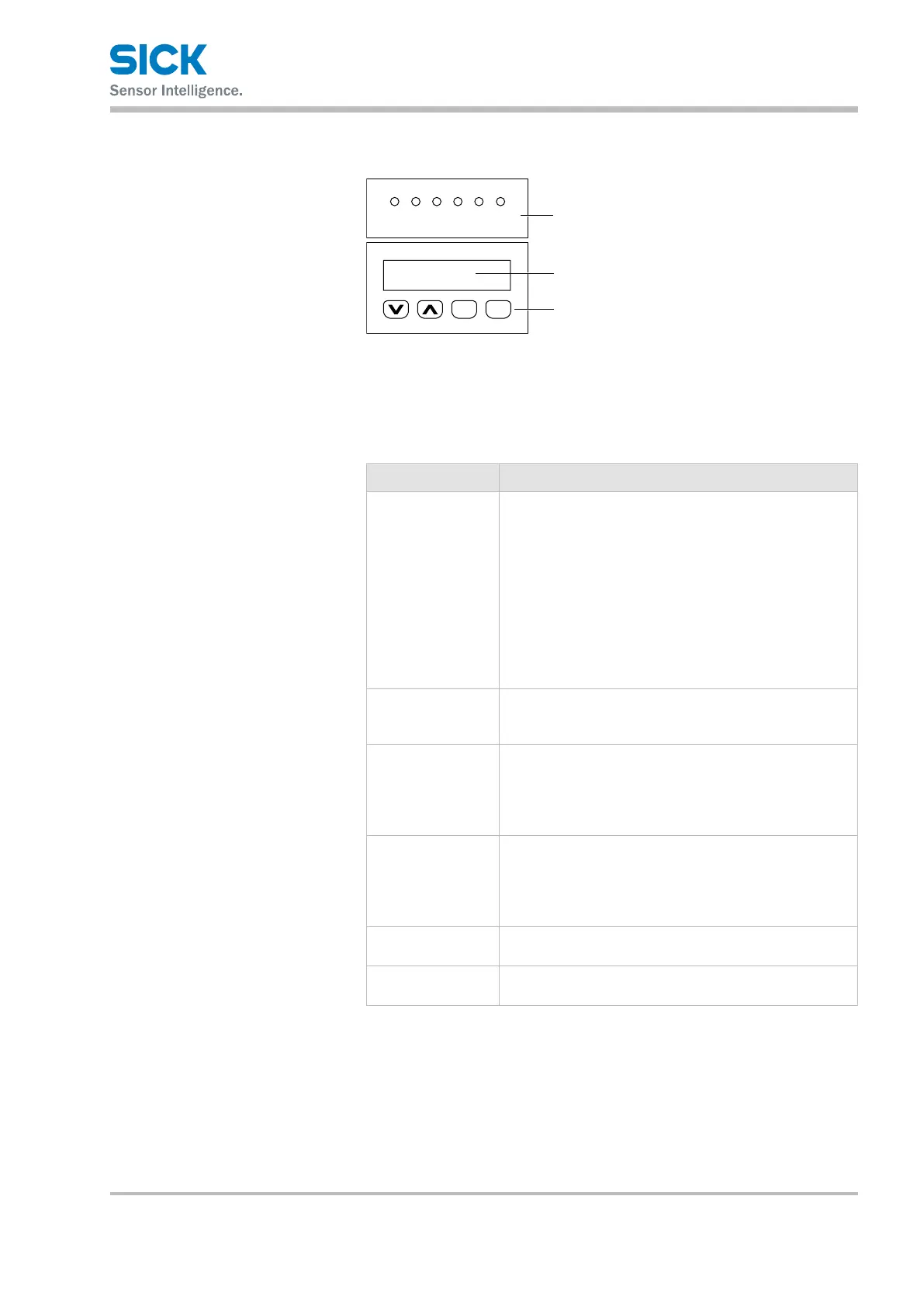
4.3 Display and operating elements
EscSet
PWR
MF1/2
LNK1
LNK2
BF
SF
Fig. 5: Display and operating elements
1 LEDs
2 Display
3 Pushbuttons
LEDs
LED Description
PWR Operating status display
• LEDo:Nooperation
• LED green: Interference-free operation
• LEDashinggreen:SSIclockavailable
• LEDashingorange:Warning(seewarningstatus–
upper level menu)
• LEDashingred:Malfunction(seeerrorstatus–
top-level menu)
→
For information on troubleshooting, see Page 112,
Chapter 13.
MF1/2
The status of the MF1 multifunctional input/output and
MF2 multifunctional output is indicated by an LED.
→ See Page 22, Table 2.
LNK1 Ethernet
• LEDo:NoEthernetavailable
• LED green: Ethernet available
• LEDashingorange:Databeingtransmitted
LNK2 Ethernet
• LEDo:NoEthernetavailable
• LED green: Ethernet available
• LEDashingorange:Databeingtransmitted
BF
PROFINET IO interface
→ See following table “BF and SF LEDs”.
SF
Bus status
→ See following table “BF and SF LEDs”.
Table 1: LEDs