8024484/2019-06-06 • © SICK AG • Subject to change without notice 41
Electrical connection
7.4 Connection diagrams
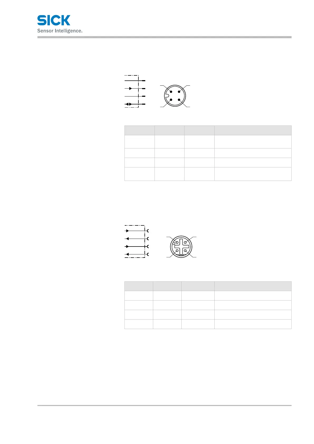
7.4.1 Supply voltage connection diagram
L+
M
MF
1
2
4
wht
blu
brn
blk
3
Fig. 23: Supply voltage connection diagram, M12 male connector, 4-pin, A-coded
Contact Labeling Wire color Description
1 L+ brown Supply voltage:
+18–30 V DC
2 MF2 white Multifunctional output MF2
3 M blue Supply voltage: 0 V
4 MF1 black MF1 multifunctional input and
output
Table 7: Description of supply voltage male connector
7.4.2 Port 1 and port 2 connection diagram (Ethernet/PROFINET IO)
Tx+
Tx–
Rx
1
2
4
wht/grn
ora
wht/ora
grn
3
Fig. 24: Port 1 and port 2 connection diagram, M12 female connector, 4-pin,
D-coded
Contact Labeling Wire color Description
1 Tx+ White/orange Send data signal, not inverted
2 Rx+ White/green Receive data signal, not inverted
3 Tx– Orange Send data signal, inverted
4 Rx– Green Receive data signal, inverted
Table 8: Description of port 1 and port 2 female contact