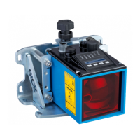
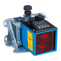
Structure and function
22 © SICK AG • Subject to change without notice • 8024484/2019-06-06
LED MF1/2
LED MF1/2 MF1 MF2
O OFF OFF
Blue ON OFF
Yellow OFF ON
White ON ON
Table 2: LED MF1/2
BF and SF LEDs
Display Description
BFo/SFo PROFINET connection OK.
Device boot-up.
BFashing/SFo Ethernet connection OK.
PROFINET boot-up.
Devicenotconguredorincorrectlycongured.
→ For troubleshooting, see Page 112, Chapter 13.1.
BFon/SFo No Ethernet cable connected.
BFoorashing/
SFashing
PROFINETstationashingtestactive
Table 3: BF and SF LEDs
Symbols for operating modes Thedevicehastwodierentoperatingmodes:“measuredvaluedisplay”
and “menu display”, which are indicated on the display by the symbols RUN
and MEN.
Symbol Description
RUN The device is in “measured value display” operating mode
when it is switched on. The RUN symbol and the current
distance value are displayed → Fig. 6.
MEN
The MEN symbol is displayed in “menu display” operating
mode. This symbol is also displayed when there is an error
and no measured value can be recorded.
Table 4: Symbols for operating modes
Pushbuttons
Pushbutton Description
• Select menu, parameter, or option.
• Decrease value.
• Select menu, parameter, or option.
• Increase value.
• Switch to the next-lowest menu level.
• Save parameter change.
• Conrmselection.
• Exit parameters without saving. Switch to the next-
highest menu level.
Table 5: Pushbuttons