Assembly and Installation
FLOWSIC100 · Operating Instructions · 8012513/YSA5/V2-1/2016-07 · © SICK Engineering GmbH 107
Subject to change without notice
3.3.8.2 Bus addressing
On bus systems (several sender/receiver units on one MCU), the required bus address of a
sender/receiver unit (master only) can be assigned by the hardware or software. Hardware
addressing is read in when SOPAS ET starts and has a higher priority than software
addressing. Software addressing is only available for SICK Service (SOPAS password level
"SICK Service").
Bus addresses and sensor numbers in the MCU (see Section 4) are always identical.
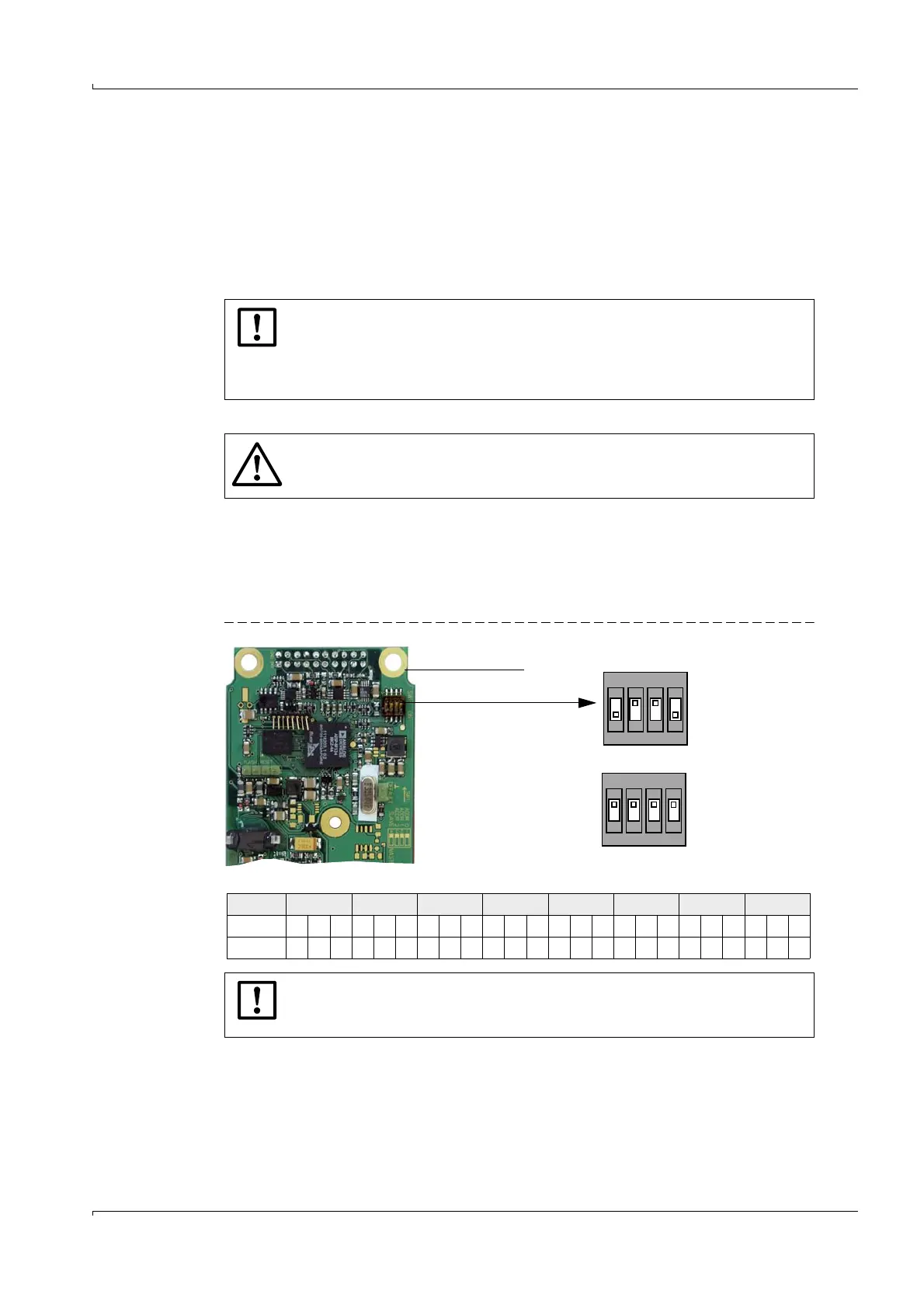
3.3.8.3 Hardware addressing
As standard, the address is set using a miniature switch on the digital board in the sender/
receiver unit (3 switches for hexadecimal addressing from address 1 to 7, see Fig. 3.2). The
address assigned to a sender/receiver unit upon delivery is noted in the electronics
housing.
Fig. 77 Hardware addressing of sender/receiver unit
3.3.9
Installing and connecting the interface and I/O module options
Plug these modules onto the top hat rail in the MCU (
p. 97, Fig. 68) and connect to the
associated connection on the processor board with the cable with plug-in connector (
p.
36, Fig. 21).
NOTICE:
After a possibly necessary change of addressing, the respective sender/
receiver units must be started anew (disconnect and reconnect supply
voltage). The output assignments in the MCU then have to be reconfigured
(see Section 4).
WARNING:
The sender/receiver units must have different addresses. Identical addresses
for several units cause the communication with the MCU to abort!
NOTICE:
Only address 1 or for two-path operation, addresses 1 and 2, may be selected
for the FLOWSIC100.
Digital board
Miniature switch
Switch 4 serves for master -
slave switch-over
Switch
1
2
3
4
Position
OFF
ON
(Switch position for address 1/master)
Address 0 1 2 3 4 5 6 7
Switch 123123123123123123123123
ON x x xx xx x xxxxx
1
2
3
4
1
2
3
4
1
2
3
4
No address reading/slave)