Product Description
FLOWSIC100 · Operating Instructions · 8012513/YSA5/V2-1/2016-07 · © SICK Engineering GmbH 27
Subject to change without notice
2.3.1.3 Purged sender/receiver units
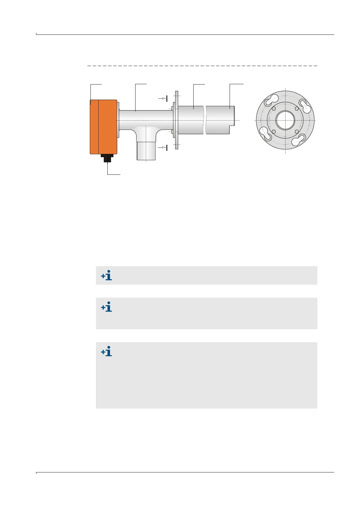
Fig. 13 FLSE100-PM, PH, PHS
These sender/receiver units are intended only for use with wet and sticky dust when the
transducer surface is in high danger of contamination. Purge air is supplied by a purge air
unit to keep the active transducer surface clean and therefore protect against
contamination (
p. 43, 2.3.9). The purge air flow is optimized to maximize the directivity of
the ultrasound beam.
An integrated temperature sensor records the transducer temperature which can then be
displayed in SOPAS ET.
NL = 200 mm (only PM and PH)
350 mm
550 mm
750 mm
NL
A
A
1 Electronics unit 4 Transducer
2 Connection piece 5 Connection for connection cable
3 Duct probe
1
2
4
3
5
A -
See the Application Range Table on page 21 for limitations of use
For dust concentrations > 1 g/m³, install the sender/receiver units at an
angle of 60° to the flow direction (only applicable for FLSE100-PH and
PHS). The downstream sender/receiver unit (B in
p. 15, Fig. 4) has to be
equipped with an impact protector.
At low gas temperatures, the purge air supply can cause the temperature to
drop below the dew point. To minimize the possible corrosion on the probe
head (for example, due to acid formation with corrosive gas compositions),
duct probes with a nominal length greater than that actually required for
the flanges with tube must be selected for temperatures between 150
°C
and 200
°C (for example, if the nominal length of the flange with tube is
350 mm
a duct probe with a nominal length of 550 mm should be
used). The purge air is then heated by the gas temperature in the probe
tube which minimizes temperature drops below the dew point.