80 FLOWSIC100 · Operating Instructions · 8012513/YSA5/V2-1/2016-07 · © SICK Engineering GmbH
Assembly and Installation
Subject to change without notice
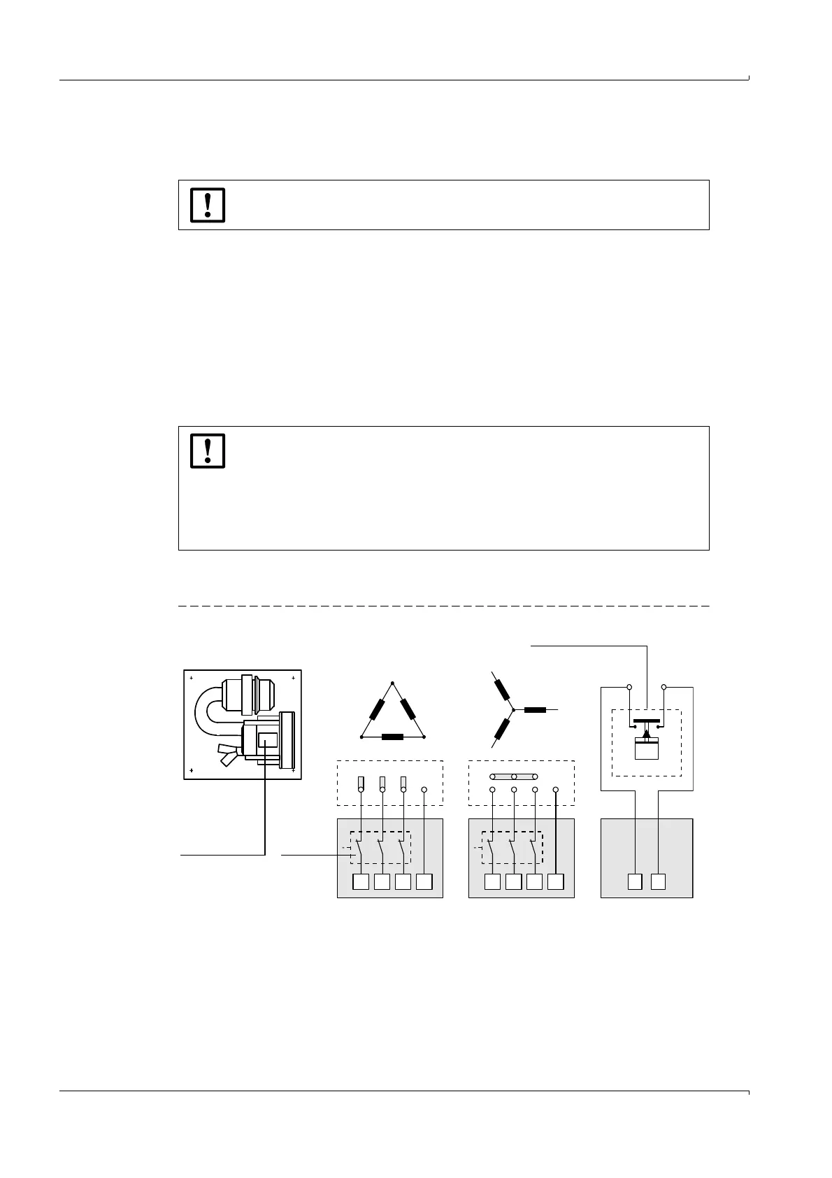
3.3.2.3 Purge air unit (device type PM, PH, PH-S)
Compare the mains voltage and frequency with those specified on the type plate of the
purge air motor.
Connect the power supply cable to the terminals on the purge air motor (see supple-
mentary sheet on purge air motor and cover of motor terminal box; connection arrange-
ment
Fig. 50).
Connect a protective conductor to the terminal.
Set the motor circuit breaker in accordance with the connection data of the blower (see
technical data of purge air unit) to a value 10% greater than the rated current.
Check the functioning and running direction of the blower (flow direction of the purge
air unit must match the arrows on the inlet and outlet openings on the blower). Incor-
rect running direction on 3-phase motors: Swap mains connections L1 and L2.
Connect the (optional) pressure controller for monitoring the purge air supply.
In case of doubt or when using a special motor version, the operating instructions supplied
with the motor have priority over any other information.
Fig. 50 Electrical connections for the purge air unit option
NOTICE:
Do not connect the purge air unit if the values do not match.
NOTICE:
Use a fail-safe power supply (emergency voltage supply, bar with redundant
supply)
The purge air unit must be fused separately from the other system
components. The fuse type must match the rated current (see technical
details of purge air unit). Fuse each phase separately. Provide circuit
breakers to protect against a phase failure on one side.
L1 L1
U1 U1
U1
U1
V1 V1
V1
V1
W1 W1
W1
W1
PE PE
W2 W2
W2
W2
V2 V2
V2
V2
U2 U2
U2
U2
L2 L2
+
Low-pressure sensor
Installed onsite
Motor
circuit
breaker
delta connection star connection
Blower motor in