Assembly and Installation
FLOWSIC100 · Operating Instructions · 8012513/YSA5/V2-1/2016-07 · © SICK Engineering GmbH 57
Subject to change without notice
3.1.3 Selecting the flanges with tube
The criteria listed under
p. 28, 2.3.2 are applicable for selection.
Inside coated ducts
The following points must also be taken into account when the inside of the duct/pipeline
is coated (rubber insulation):
● Since the inside of the flange tubes also has to be coated, it might be necessary to
select flange tubes with a larger inside diameter. The minimum distance between the
probe tube and flange tube is 3 mm.
● If a standard flange with tube cannot be used, make the flanges with tube onsite (deliv-
erable by SICK on request).
● To ensure coating is complete, the flanges must be mounted before being coated.
Plastic ducts
The standard flanges with tube generally cannot be used for plastic ducts/pipelines.
Possible solutions (to be carried out onsite):
● On GRP ducts
1:
Laminate the steel core with pitch diameter of the mounting holes. The
inside diameter of the laminated flange tube must match the selected FLSE100.
● Use flanges with tube made from duct/pipe material; weld-mount or fit with plastic
adhesive.
● Mount adapter flanges on openings prepared onsite.
Determining the nominal length
The required nominal length of the flanges with tube can be determined using the following
Figures.
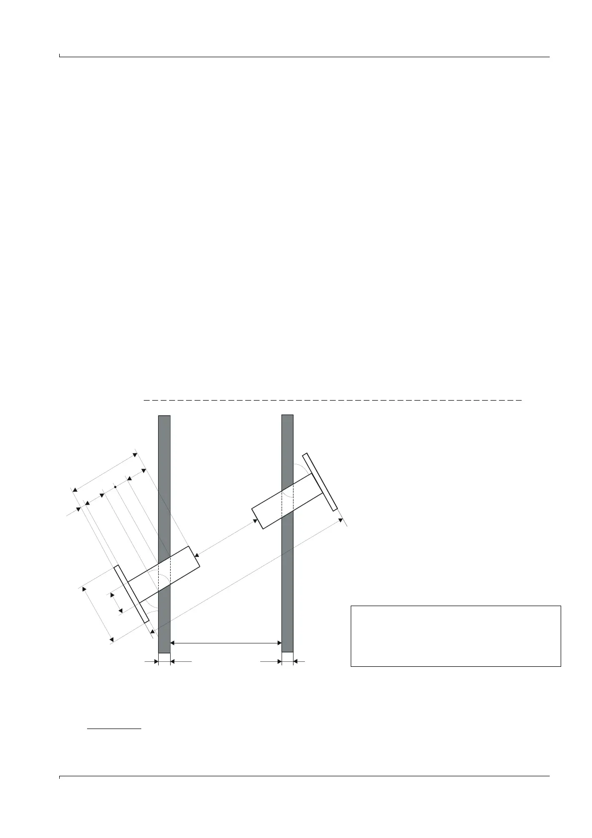
Fig. 31 Determining the nominal length of the flanges with tube
1 GRP = glass fiber reinforced plastic
Lf = Length of flange with tube (minimum)
Le = Draw-in length (min. 20)
D
A
= Outer diameter of flange
D
R
= Outer diameter of tube
= Installation angle
s = Flange thickness = 10
L = Active measuring path (input value)
w = Thickness of duct wall + insulation
Di = Inside diameter of duct
L
F
s
L
a
L
e
L
w
L
d
D
A
D
R
w
Di
a
L
a
b
b
a
a
w
b = 90°- a
Dimensions in mm
La
min
D
A
D
R
–
2
---------------------------
tan=
L
Fmin
s
D
A
D
R
+
2
---------------------------
+90–tan
w
sin
-----------
Le++=
L
Di
sin
-----------
2Le Ld––=