98 FLOWSIC100 · Operating Instructions · 8012513/YSA5/V2-1/2016-07 · © SICK Engineering GmbH
Assembly and Installation
Subject to change without notice
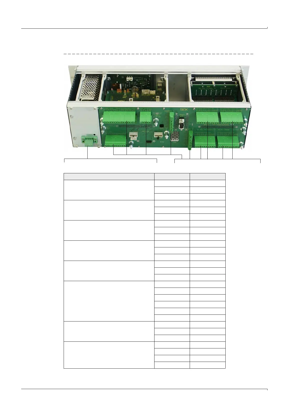
3.3.7 Connecting the control unit in a 19" housing
Fig. 69 Connections on the MCU as 19" version
Terminal connection for power supply 90 - 250 VAC
Terminal connection for wiring by customer
Function Connection Terminal No.
Output relay 1 (operation/malfunction) com 1
n.c.
1)
2
n.o.
2)
3
Output relay 2 (maintenance) com 4
n.c.
1)
5
n.o.
2)
6
Output relay 3 (check cycle) com 7
n.c.
1)
8
n.o.
2)
9
Output relay 4 (maintenance request) com 10
n.c.
1)
11
n.o.
2)
12
Output relay 5 (limit value) com 13
n.c.
1)
14
n.o.
2)
15
Digital input d in 1 16
d in 2 17
gnd 18
d in 3 19
d in 4 20
gnd 21
Analog output + 22
-23
gnd 24
Analog input a in 1 25
gnd 26
a in 2 27
gnd 28