Assembly and Installation
FLOWSIC100 · Operating Instructions · 8012513/YSA5/V2-1/2016-07 · © SICK Engineering GmbH 81
Subject to change without notice
3.3.2.4 Installing the purge air and cooling air reducer option
If necessary, install a purge air reducer for FLOWSIC100 PM, PH, PHS or a cooling air
reducer for FLOWSIC100 MAC, HAC according to
Fig. 51.
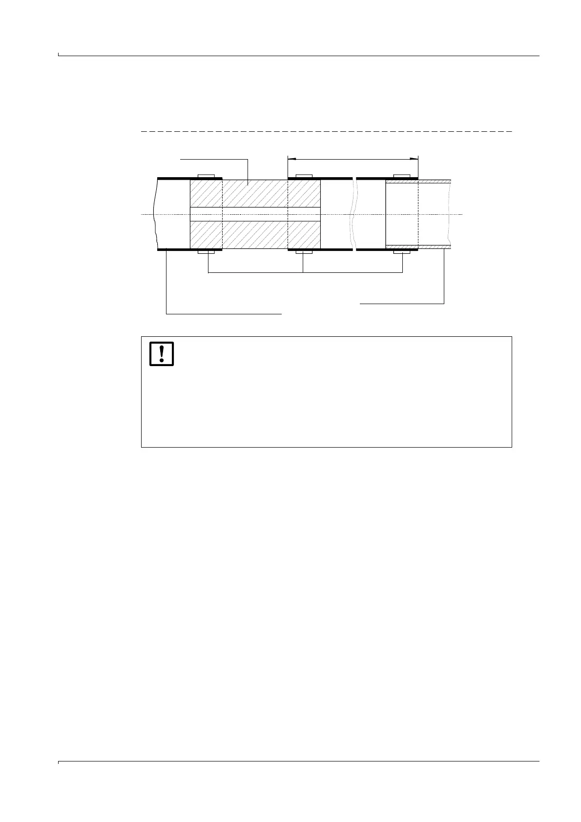
Fig. 51 Purge air unit
NOTICE: Cooling air reducer for FLOWSIC100 MAC, HAC
Usually, it is not necessary to install the reducing pieces during regular
operation.
Installation can become necessary when the measuring system runs in an
extreme range due to unfavorable application conditions and noise effects
of the cooling air have to be reduced.
In particular cases, the effectiveness of the cooling air reducer has to be
checked by a trained service technician during start-up of the measuring
system.
approx. 200 mm
Reducer
Purge air/cooling air hose to
the sender/receiver unit
Clamping tape
Purge air/cooling air
unit hose connection