176 FLOWSIC100 · Operating Instructions · 8012513/YSA5/V2-1/2016-07 · © SICK Engineering GmbH
Specification
Subject to change without notice
6.3.3 MCU control unit
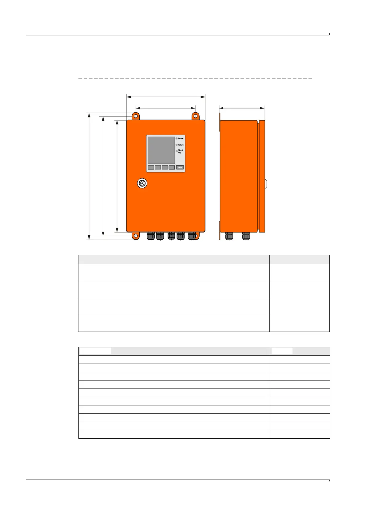
Control unit MCU-N (without integrated cooling air supply)
Fig. 144 Control unit MCU-N (with display module option)
Options
Designation Part No.
MCU-NWONN00000NN control unit in wall housing (orange),
Supply voltage 90 ... 250 V AC, without display
1040667
MCU-NWODN00000NN control unit in wall housing (orange),
Supply voltage 90 ... 250 V AC, with display
1040675
MCU-N2ONN00000NN control unit in wall housing (orange),
Supply voltage 24 V DC, without display
1040669
MCU-N2ODN00000NN control unit in wall housing (orange),
Supply voltage 24 V DC, with display
1040677
Designation Part No.
Analog input module (AI) 2034656
Analog output module (AO) 2034657
Digital output module: 2 channels (changeover contact) 2034659
Digital output module: 4 channels (make-contact) 2034661
Slot rail for fitting one each AI, AO, DO module 6033578
Profibus DP interface module with MCU connection cable 2048920
Ethernet interface module with MCU connection cable 2055719
Ethernet interface module, 3-fold, with MCU connection cable 2072693
Modbus RS485 interface module with MCU connection cable 2048958
Modbus TCP interface module with MCU connection cable 2059546