Specification
FLOWSIC100 · Operating Instructions · 8012513/YSA5/V 2-1/2016-07 · © SICK Engineering GmbH 183
Subject to change without notice
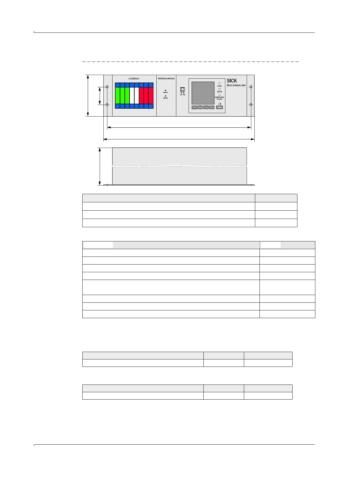
6.3.7 Control unit, MCU 19“
Fig. 150 Control unit, MCU in 19" slot (shown with display module option)
Options for MCU control unit in 19" slot
6.3.8 Consumable parts for 2-years operation
6.3.9 Control unit MCU with integrated purge air supply
6.3.10 Optional external purge air unit
Designation Part No.
Control unit, MCU-NWPD in 19" housing 1046117
Control unit, MCU-NWTD in 19" housing 1046288
Control unit, MCU-N2RD in 19" housing 1046116
132,5
57,15
465,9
482,6
Approx.
*: Including
clearance for
cables
Designation Part No.
Analog input module (AI) 2034656
Analog output module (AO) 2034657
Digital output module: 2 channels (changeover contact) 2034659
Digital output module: 4 channels (make-contact) 2034661
I/O module carrier, 19”
(for installing up to 4 AI/AO modules and 4 DI/DO modules)
2050589
Interface module 19” Profibus DP with connection cable 2049334
Interface module 19” Ethernet with connection cable 2048377
Interface module 19“ Modbus RS485 with connection cable 2050674
Designation Number Part No.
Filter element C1140 4 7047560
Designation Number Part No.
Filter element Micro-Topelement C11 100 4 5306091