Assembly and Installation
FLOWSIC100 · Operating Instructions · 8012513/YSA5/V2-1/2016-07 · © SICK Engineering GmbH 69
Subject to change without notice
3.2.6 Installing the purge air unit option (device type PM, PH, PH-S)
The steps below are only necessary when purged sender/receiver units are required.
The following points must be taken into account when selecting the installation location:
● The purge air unit must be installed in a location with clean air. The intake temperature
must match the values specified in the Technical Data (
p. 166, 6.1). If necessary, lay
an air intake hose at a location where conditions are more favorable.
● The fitting location must be easily accessible and meet all applicable safety require-
ments.
● The purge air unit must be mounted as far below the sender/receiver units as
necessary, so that the purge air hoses can be installed leading downwards to the purge
air unit (avoiding water collection).
● Provide sufficient clearance for replacing the filter element.
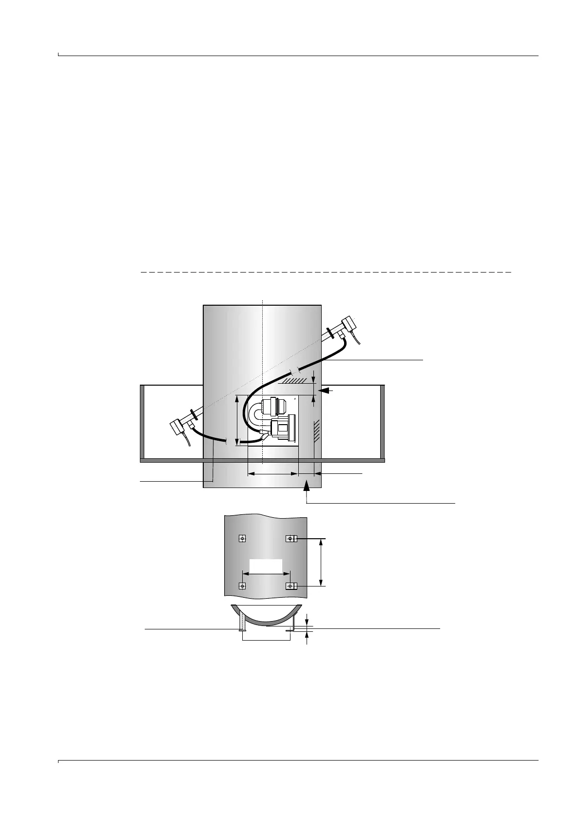
● Provide sufficient clearance for fitting and raising the weatherproof cover when the
purge air unit is installed outdoors (
Fig. 40).
Fig. 40 Mounting the purge air unit
> 160
(550)
Duct
Clearance for replacing filter element
> 140
(550)
Purge air hose
Purge air hose
Clearance
for fitting of
weather-
proof cover
470
470
Alternative: Mounting bracket
50 x 5 steel pipe
DIN 2391
50
M 8