Product Description
FLOWSIC100 · Operating Instructions · 8012513/YSA5/V2-1/2016-07 · © SICK Engineering GmbH 17
Subject to change without notice
2.3 System components
2.3.1 FLSE100 sender/receiver unit
The sender/receiver unit consists of the electronics, connector, duct probe, and transducer
modules. These modules are available in different versions that can be combined on the
basis of the relevant application data to produce the optimum configuration for the
application in question.
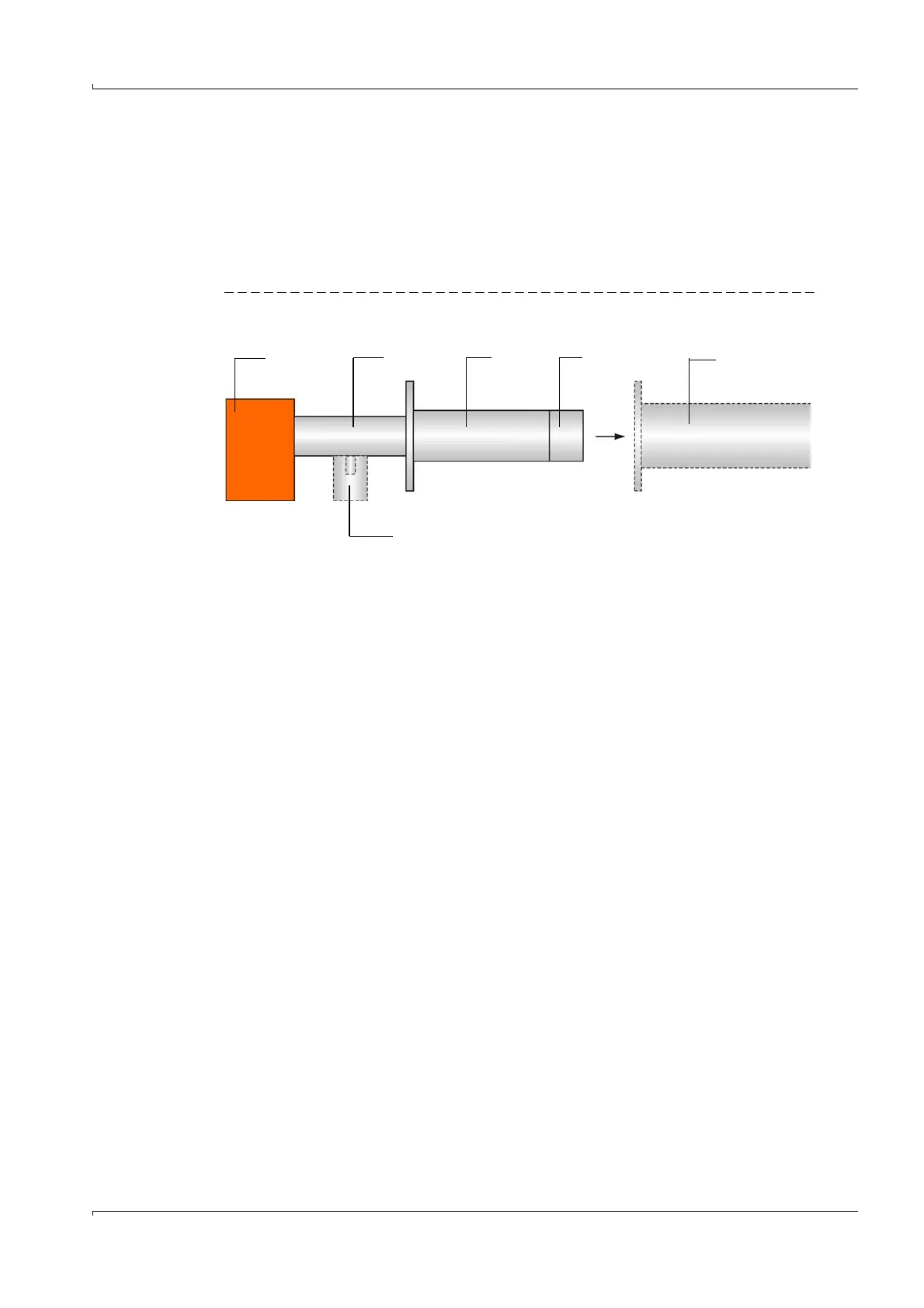
Fig. 5 Schematic diagram with modules of the sender/receiver unit and flange with tube
1
1 Electronics unit 4 Transducer
2 Connection piece 5 Flange with tube
3 Duct probe 6 Purge air connection (only for purged versions PM, PH, PHS)
Cooling air connection (only for internally cooled versions MAC, HAC)
2
34
5
6