Product Description
FLOWSIC100 · Operating Instructions · 8012513/YSA5/V2-1/2016-07 · © SICK Engineering GmbH 13
Subject to change without notice
2.2 System overview and functional principle
2.2.1 System overview
The measuring system comprises the following components:
● FLSE100 sender/receiver unit
For transmitting and receiving ultrasonic pulses, signal processing and controlling the
system functions
● Flange with tube
For mounting the sender/receiver units on the gas duct
● MCU control unit
For control, evaluation and output of the data of the sensors connected via RS485
interface
● Connection cables
For signal transmission between the sender/receiver units and control unit
● Junction box for connection cable
For connecting the connection cables
● Purge air unit option
For using purged sender/receiver units to keep the ultrasonic transducers clean and
cool at high gas temperatures
● Cool air unit option
For using internal cooled sender/receiver units to keep the ultrasonic transducers cool
at high gas temperatures
● Measuring tube option
Tube piece with flanges, preassembled for installation in an existing pipeline; with
flanges with tube to fit the sender/receiver units
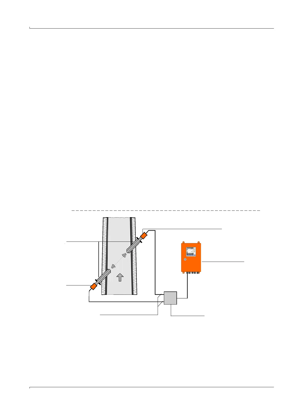
Fig. 1 FLOWSIC100 system components
● Cooling air control option for device types M-AC and H-AC
Used to control the cooling air supply for sender/receiver units with internal cooling by
switching the cooling air blower on and off automatically depending on the transducer
temperature.
● Emergency air supply option for sender/receiver units with internal cooling (FLSE100-
MAC and HAC)
Set for connecting and operating a temporary emergency air supply of instrument air (to
be provided by customer) for sender/receiver units with internal cooling.
● Emergency air supply option for externally purged sender/receiver units (FLSE100-PM,
PH, PH-S)
Sender/receiver unit
FLSE100 Slave (B)
Duct
MCU control unit
Connection cable
Junction box
Sender/receiver
unit FLSE100
Master (A)
Flange with tube