Product Description
FLOWSIC100 · Operating Instructions · 8012513/YSA5/V2-1/2016-07 · © SICK Engineering GmbH 15
Subject to change without notice
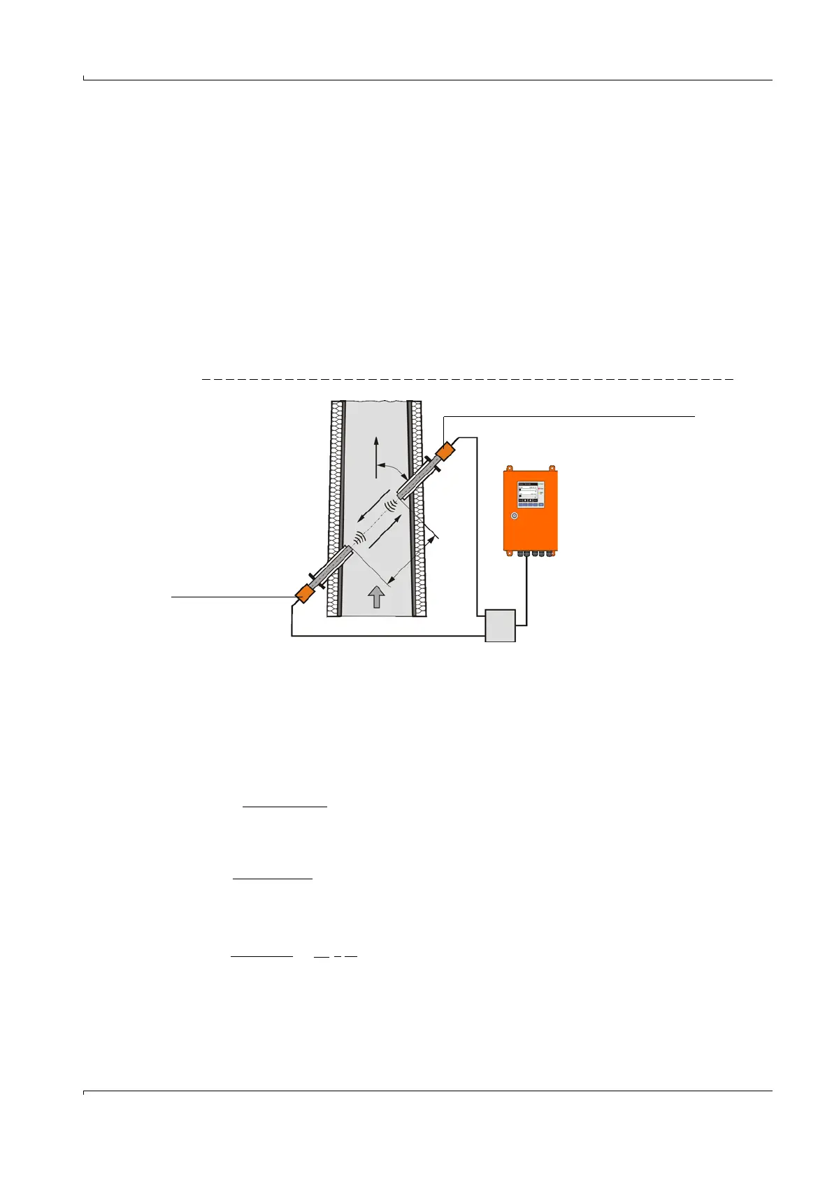
2.2.3 Functional principle
The FLOWSIC100 gas flow rate measuring devices operate according to the principle of
ultrasonic transit time difference measurement. Sender/receiver units are mounted on
both sides of a duct/pipeline at a certain angle to the gas flow (
Fig. 4).
These sender/receiver units contain piezoelectric ultrasonic transducers that function
alternately as senders and receivers. The sound pulses are emitted at an angle to the
flow direction of the gas. Depending on the angle and the gas flow rate v, the transit time
of the respective sound direction varies as a result of certain "acceleration and braking
effects" (formulas 2.1 and 2.2). The higher the gas flow rate and the smaller the angle to
the flow direction are, the higher the difference in the transit times of the sound pulses.
Gas flow rate v is calculated from the difference between both transit times, independent
of the sound velocity value. Therefore changes in the sound velocity caused by pressure or
temperature fluctuations do not affect the calculated gas flow rate with this method of
measurement.
Fig. 4 Functional principle of the FLOWSIC100
Calculating the gas flow rate
Measuring path L is equal to the active measuring path, that is, the area through which the
gas flows. Given measuring path L, sound velocity c, and angle of inclination between the
sound and flow direction, the sound transit time in the direction of the gas flow (forward
direction) when the signal is transmitted can be expressed as:
(2.1)
Against the gas flow (backward direction):
(2.2)
After the resolution to v:
(2.3)
Apart from the two measured transit times, this relation only contains the active measuring
path and the angle of inclination as constants.
Sender/receiver unit FLSE100 - Slave (B)
v = Gas flow rate in m/s
L= Measuring path in m
= Angle of inclination in °
t
v
= Signal transit time
in flow direction
t
r
= Signal transit time
against flow direction
Sender/receiver
unit
FLSE100 Master (A)
t
v
v
a
t
r
L
v = · ()
L 1 1
2 · cos t
v
t
r
t
r
=
L
c - v · cos
t
v
=
L
c + v · cos