106 FLOWSIC100 · Operating Instructions · 8012513/YSA5/V2-1/2016-07 · © SICK Engineering GmbH
Assembly and Installation
Subject to change without notice
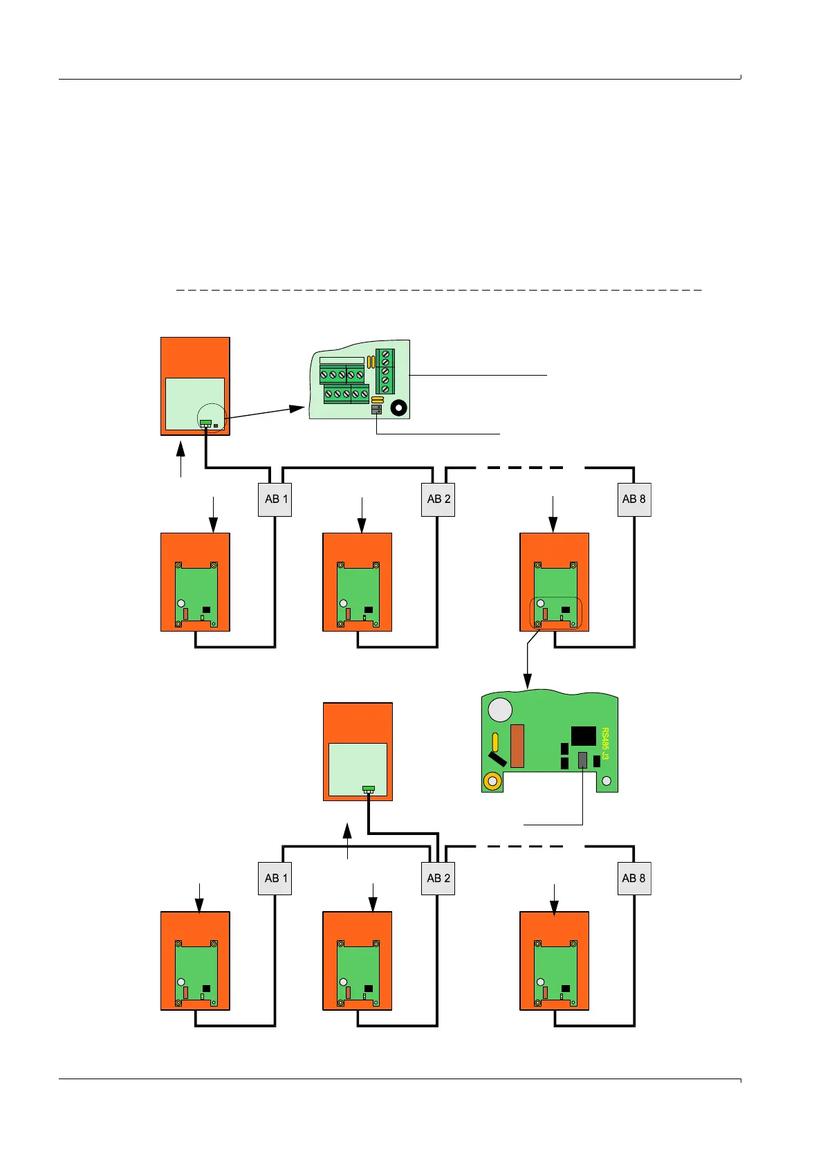
3.3.8 Terminating the sender/receiver units when operating the FLOWSIC100 with
"2-path measuring" configuration
3.3.8.1 Checking the sender/receiver unit(s) - MCU connection
Checking the termination
The connection between sender/receiver units and MCU must be terminated at the start
and end with resistors for both single and bus wiring. The terminating resistors are already
on the circuit boards and are activated by
plugging jumpers on the respective pins.
Fig. 76 Termination of bus wiring
FLSE100
Master
FLSE100
Master
FLSE100
Master
FLSE100
Master
MCU at bus start
MCU in bus middle
Processor board
Jumper
Jumper
AB x = junction box x
T = termination
required
k = no termination
Tk k T
Tkk T