28 FLOWSIC100 · Operating Instructions · 8012513/YSA5/V2-1/2016-07 · © SICK Engineering GmbH
Product Description
Subject to change without notice
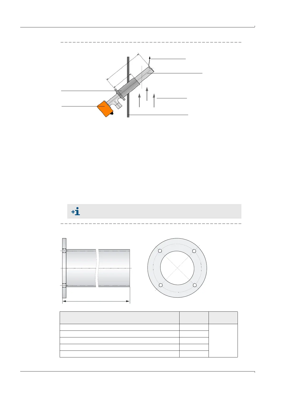
Fig. 14 Using sender/receiver units with a nominal length greater than the flange with tube
2.3.2 Flange with tube
The sender/receiver units are mounted in flanges with tube available in graded nominal
lengths, different steel types and pitch diameters.
Selection of a flange with tube depends on:
● Installation angle and wall and insulation thickness of duct wall
Determining the nominal length (Assembly and Installation Chapter,
p. 49)
● Type of sender/receiver unit
Pitch diameter of flange, pipe diameter
● Duct material
Steel type
Fig. 15 Flange with tube
Flange with tube
Sender/receiver
unit
Purge air
Area heated by
the gas flow
Gas flow
Duct wall
N
L
F
L
S
E
1
0
0
N
L
F
NL
FLSE100
= Nominal length sender/receiver unit
NL
F
= Nominal length flange with tube
If required, the flanges with tube can also be delivered in advance.
L
L = NL - 12
Type FLSE100 Nominal
length in mm
Material
S 125
St37, V4A
(others on
request)
S, M, PM, PH 200
S, M, MAC, H, HAC, PR, PM, PH, PHS 350
M, MAC, H, HAC, PR, PM, PH, PHS, 550
H, PR, PM, PH, PHS 750