146 FLOWSIC100 · Operating Instructions · 8012513/YSA5/V2-1/2016-07 · © SICK Engineering GmbH
Start-up and Parameter Settings
Subject to change without notice
The boxes to set the parameters for further analog outputs 2/3 or 4/5 are open for
input.
Set the parameters for further analog outputs as described for setting the parameters
for the first analog output.
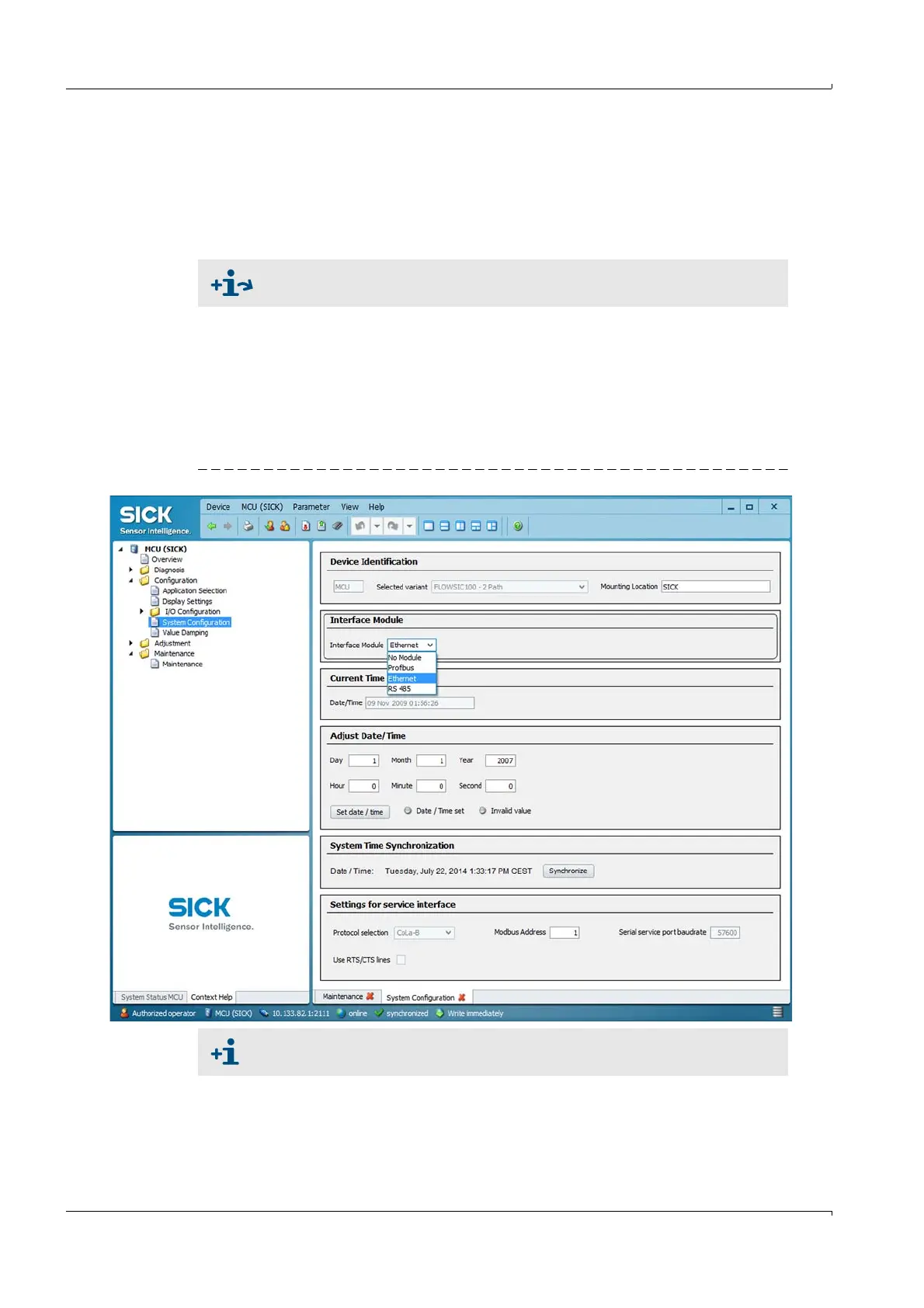
4.3.3 Configuring the optional interface module
The following steps are required for selecting and configuring the optionally available
interface module:
Select device file "MCU", set the measuring system to "Maintenance" mode and enter
the Level 1 password (
p. 124, Table 3).
Select directory "Configuration / System Configuration".
The installed interface module is displayed in the field "Installed Interface Module".
Configure the interface module according to requirements.
Fig. 124 "Configuration / System Configuration" directory
For detailed information on the individual modules see "Interface
Documentation FLOWSIC100".
GSD file and measured value assignment are available for the Profibus DP
module on request.