126 FLOWSIC100 · Operating Instructions · 8012513/YSA5/V2-1/2016-07 · © SICK Engineering GmbH
Start-up and Parameter Settings
Subject to change without notice
4.2 Standard start-up procedure
This Section describes all the settings essential to ensure the device functions correctly.
These include entering system data (active measuring path, installation angle, cross-
sectional area) and creating the check cycle, analog output, analog inputs (to read in
external signals) as well as the damping time.
Configuring the device runs using SOPAS ET on the system components "FLOWSIC X
(Sensor)" and control unit "MCU" as follows:
To set/change the parameters, carry out the following procedure:
Connect the measuring system to program SOPAS ET, scan the network and add the
required device file ("MCU", "FLOWSIC100 X (sensor)") to the current project.
Enter the Level 1 password (
p. 125, Fig. 99) and set the relevant system components to
"Maintenance" operating mode (
p. 127, §4.2.1).
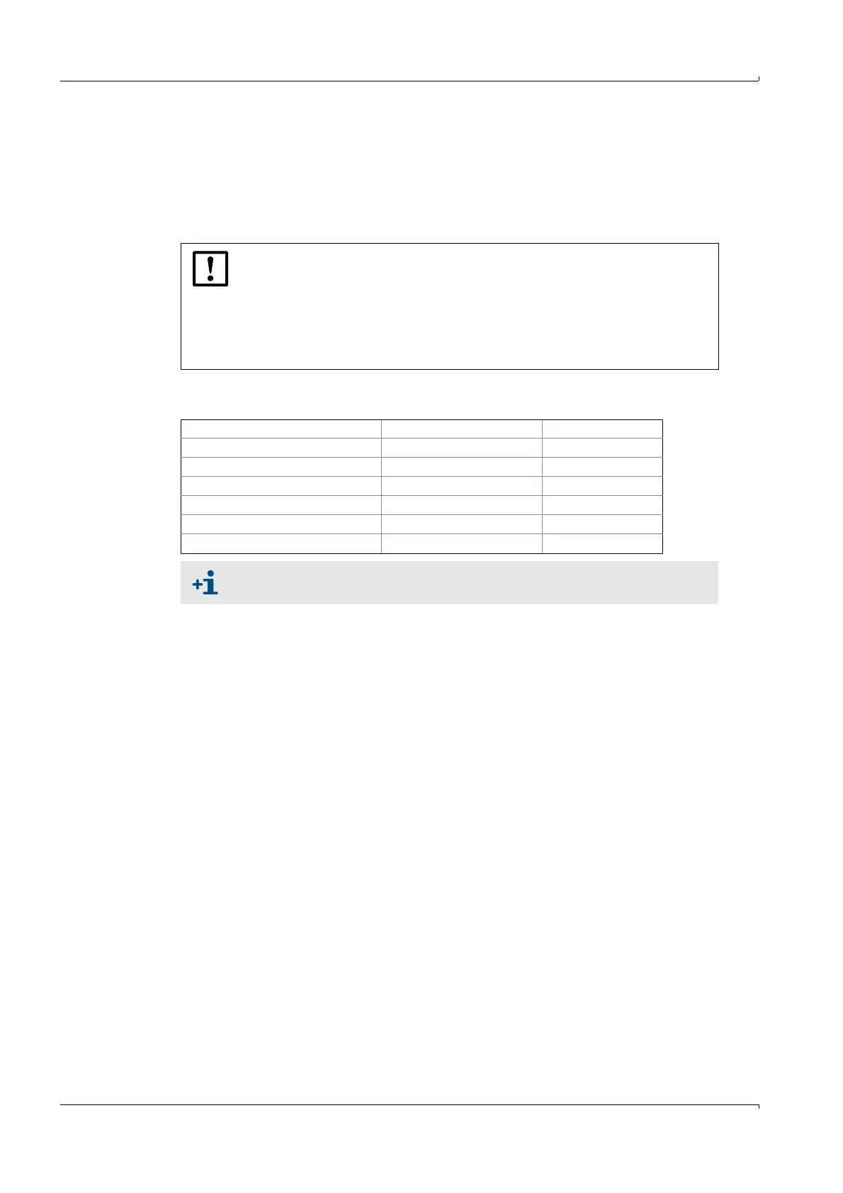
NOTICE:
● Error message "Error Parameter" is output as long as the system data have
not been entered completely on the system component "FLOWSIC100 X
(Sensor)".
● Parameter settings can only be made when the relevant system component
"FLOWSIC X (Sensor)" or control unit "MCU" is in the "Maintenance" operat-
ing state.
Setting FLOWSIC X (Sensor) MCU
Measuring path X
S/R unit(s) installation angle X
Cross-sectional area X
Reaction time X
Check cycle X
Standard analog output X
Calibration settings
p. 144, 4.3