22 FLOWSIC100 · Operating Instructions · 8012513/YSA5/V2-1/2016-07 · © SICK Engineering GmbH
Product Description
Subject to change without notice
Duct probe configuration options
2.3.1.1 Standard sender/receiver units
A special transducer design makes it possible to use these sender/receiver units without
cooling by external purge air even with higher gas temperatures. A purge air unit is
therefore not necessary. The advantages are:
● Lower expense for mounting and installation
● Easier maintenance
● Lower operating costs.
For these reasons, standard sender/receiver units should be used where possible.
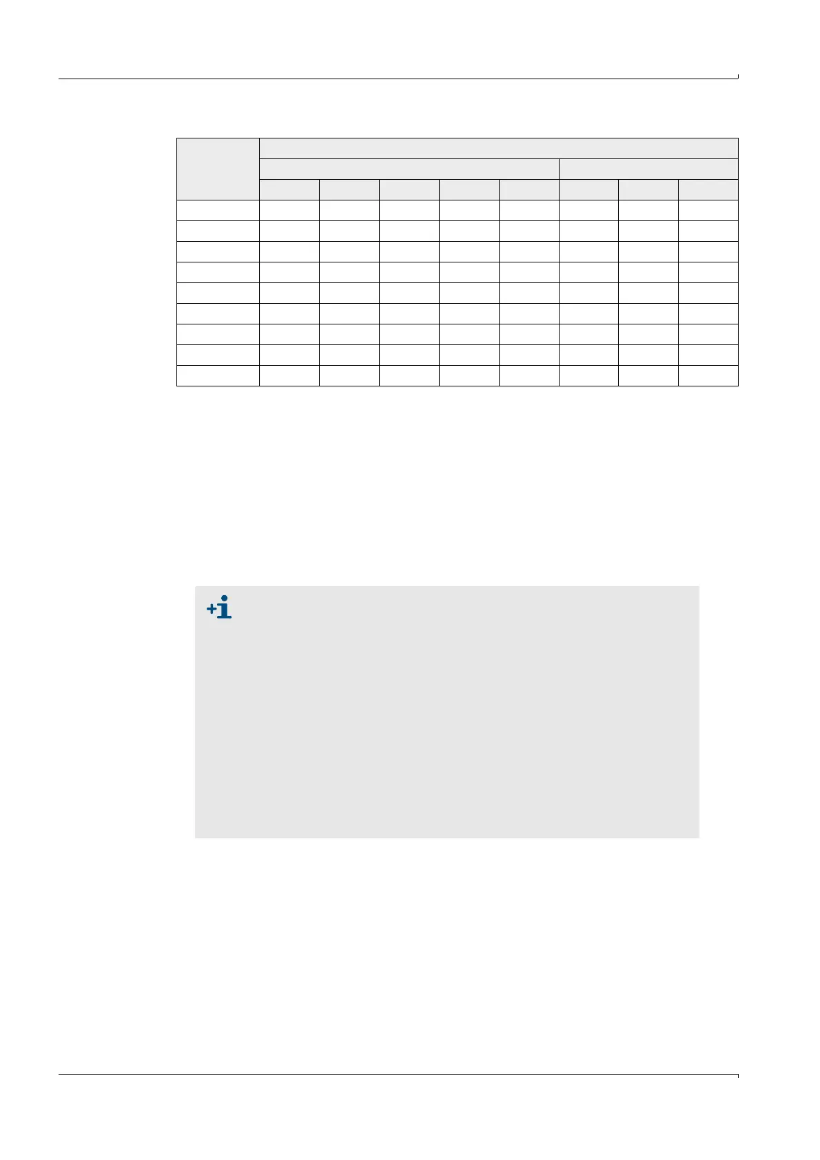
Type FLSE100
Duct probe
Nominal length in mm Material
125 200 350 550 750 SS TI HS
M xxx xxx
H xxxxxxx
PR xxxxx
SA/SD xxx x
MAC x x x x
HAC x x x x
PM xxxxx
PH xxxxxx
PHS x x x x
● The types FLSE100-M, H and PR are intended for use with gas
temperatures up to max. 260
°C. The types FLSE100-SA and SD are
intended for use up to 150°C.
● The measuring system FLOWSIC100 S contains one sender/receiver
unit FLSE100-SA and FLSE100-SD and one connection cable between
the sender/receiver units.
● The type FLSE100-SA has no electronics unit. Communication to the
FLSE100-SD as master (which communicates with the MCU control
unit) runs via an analog connection cable (fixed length: 3m). Install one
FLSE100-SA and one FLSE100-SD per sampling point (1-path configu-
ration).
● Fit the sender/receiver units at an angle of 60° to the flow direction for
dust concentrations > 1 g/m³ (only applicable for FLSE100-H, H-AC, PH
and PH-S). The downstream sender/receiver unit (B in
p. 15, Fig. 4) has
to be equipped with an impact protector.