Product Description
FLOWSIC100 · Operating Instructions · 8012513/YSA5/V2-1/2016-07 · © SICK Engineering GmbH 39
Subject to change without notice
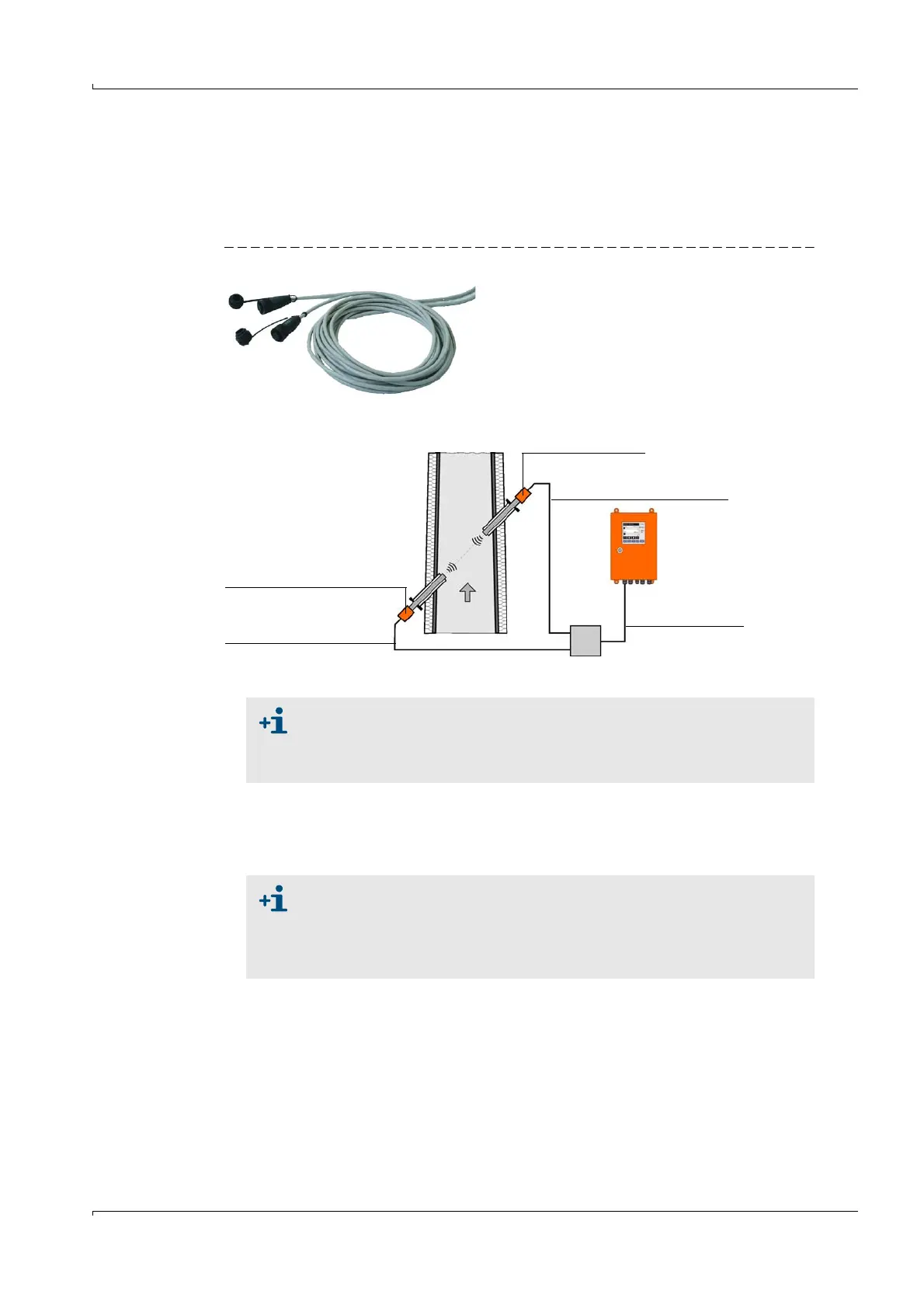
2.3.5 Connection cable
The connection cables master (Master FLSE100) and slave (Slave FLSE100) are used to
connect the sender/receiver units with the control unit MCU. Both cables are available in
different lengths. The connection cable master is marked with a red marker behind the
cable box.
Fig. 22 Connection cable
We recommend cable type UNITRONIC Li2YCYv(TP) 2x2x0.5 mm
2
with reinforced outer
sheath (from Lappkabel).
The total length of the cable between junction box and MCU (onsite cable) can be up to
1000 m.
Onsite cable
Standard cables
Master (lengths 5 m, 10 m, 50 m)
Slave (5 m, 10 m, 50 m)
FLSE100 Master (A)
FLSE100 Slave (B)
Connection cable, Master
(Li2YCYv(TP) 3x2x0.5 mm²)
Connection cable, Slave
(Li2YCYv(TP) 2x2x0.5 mm²)
Cables provided onsite must fulfill the following requirements (see also
page 97, § 3.3.6):
● Lead/lead operational capacity less than 110 pF/m
● Min. lead cross-section 0.5 mm
2
(AWG20).
When connecting bus versions with several sensors (
p. 14, Fig. 3), the max-
imum cable length is reduced as follows depending on the number of sam-
pling points connected:
● Cable length with + 1 sampling point = 1000 m
● Cable length with + 2 sampling points = 500 m