66 FLOWSIC100 · Operating Instructions · 8012513/YSA5/V2-1/2016-07 · © SICK Engineering GmbH
Assembly and Installation
Subject to change without notice
3.2.2 Installing the control unit
The control unit must be mounted on a level base at an accessible, protected location as
shown in Fig. 38. The following must be taken into account:
● Maintain the ambient temperature range in accordance with the Technical Data under
consideration of possible radiant heat (shield when necessary).
● Protect the unit from direct sunlight.
● Select an installation location free from vibrations when possible and stabilize vibra-
tions when necessary.
● Provide sufficient clearance for cables and opening the front panel.
Providing suitable cables are used (see Section
p. 97, 3.3.6), the MCU-N control unit
(version without integrated blower) can be installed up to 1000 meters from the sender/
receiver unit (use bus lines in accordance with Fig. 73; length is the overall length of all
cables). For easier access to the MCU, we recommend installing it in a control room
(measuring station or similar). This facilitates communication with the FLOWSIC100 for
configuration or troubleshooting.
If the device is to be installed outdoors, a weatherproof cover for the control unit or
equivalent cover (corrugated roof) must be provided onsite.
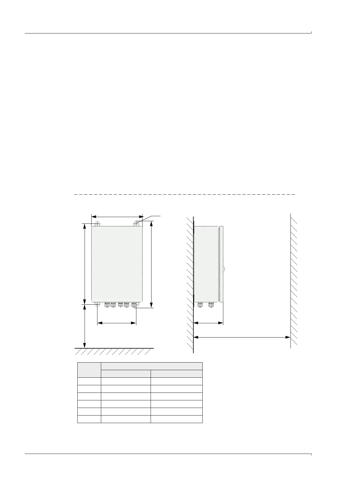
Assembly dimensions
Fig. 38 MCU assembly dimensions
c
f
e
> 250
d
b
M8
Clearance for opening the door
Clearance for cable
a
Measure Connection unit type
MCU-N MCU-P
a 160 260
b 320 420
c 210 300
d 340 440
e 125 220
f > 350 > 540
MCU-N: Control unit without
cooling air supply
MCU-P: Control unit with
cooling air supply
(
p. 176, 6.3.3)