102 FLOWSIC100 · Operating Instructions · 8012513/YSA5/V2-1/2016-07 · © SICK Engineering GmbH
Assembly and Installation
Subject to change without notice
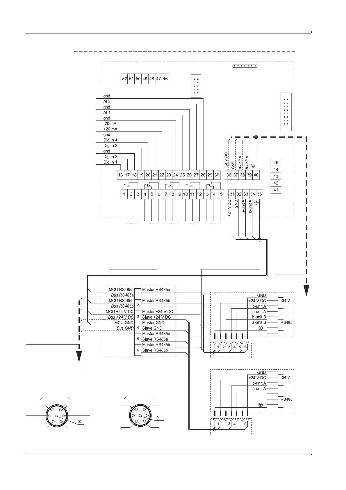
Fig. 73 FLOWSIC100 connection on the MCU (apart from types PR, S)
MCU
FLSE100 A (Master)
FLSE100 B (Slave)
Plug-in connectors
Connection cable, Master
(length 5/10/50 m)
Plug-in connectors
Junction box
Onsite cable
Processor board
Connection cable, Slave
(with red cable marking; length 5/10 m)
Plug-in connector assign-
ment, Slave: Top view
RS485 to Master
43
61
BN WH
GN YE
RS485 to MCU
43
61
BN WH
GN YE
52
WH
BN
GN
YE
G
F
A Operation/malfunction
B Maintenance
C Check cycle
D Warning
E Limit values
F Onsite cable to second junction box
For bus cabling (two-path measurement), version B
G Onsite cable to second junction box
For bus cabling (two-path measurement), version A
A
BCD
E
BL
BL
PK
Plug-in connector assign-
ment, Master: Top view
GN
YE
WH
BN
GN
YE
WH
BN
GN
YE
WH
BN
WH
BN
GN
YE