166 FLOWSIC100 · Operating Instructions · 8012513/YSA5/V2-1/2016-07 · © SICK Engineering GmbH
Specification
Subject to change without notice
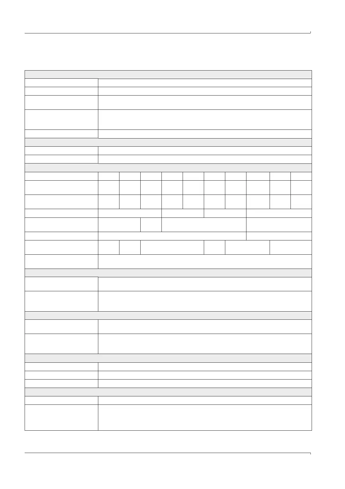
6.1 Technical Data
Measured value recording
Measured variables Gas flow rate, volume flow act., volume flow std., gas temperature, sound velocity
Measuring range Min. limit -40 to 0 m/s, max. limit from 0 to +40 m/s; continuously variable
Accuracy of emission measure-
ment
1)
±0.1 m/s
Reproducibility of
process measurement, standard
sender/receiver units
±1% for v > 2 m/s; ±0.02 m/s for v < 2 m/s
Damping time 1 ... 300 s; freely selectable
Displays
LC-Display For measured variables, warning and malfunction messages
LED Voltage supply OK, malfunction, maintenance request
Installation
FLSE100 M H PR SA SD MAC HAC PM PH PHS
Measuring path
transducer–transducer [m]
2)
0.2 - 4
3)
2 - 15
4)
0.27 -
0.28
0.2 - 2 0.2 - 2 0.2 - 4 2 - 13 0.5 - 3 1 - 10 2 - 13
Internal duct diameter [m]
5)
0.15 -
3.4
1.4 - 13 > 0.40 0.15 -
1.7
0.15 -
1.7
0.15 -
3.4
1.4 -
11.3
0.35 - 2.5 0.7 - 8.7 1.4 -
11.3
Gas temperature [°C] -40 ... +260 -40 ... +150
-40 ... +450
-40 ... +450
Installation angle (recommended)
[°]
6)
45 ... 60 45 45 ... 60 45 ... 60
Internal duct pressure [bar] ± 0.1 ±0.03
7)
; ±0.1
8)
Max. dust concentration
[g/m³ std.]
9)
1 100
10)
1 100
10)
100
Cable length between
junction box and MCU [m]
Max. 1000
Output signals
Analog output 0/2/4 ... 22 mA, max. load 750 ; resolution 12 bits;
further analog outputs with I/O modules (option)
Relay outputs 5 potential-free outputs (changeover contacts) for status signals operation/malfunction, limit value,
warning, maintenance, check cycle; load 48 V, 1 A (low voltage protection);
Further relay outputs with I/O modules (option)
Input signals
Analog inputs 2 inputs 0 ... 5/10 V or 0 ... 20 mA (without electric isolation); resolution 10 bits;
further analog inputs with I/O modules (option)
Digital inputs 4 potential-free contacts for connection of maintenance switch, activation of check cycle, separate
zero point control, separate span test;
Further digital inputs with I/O modules (option)
Communication interfaces
USB 1.1, RS232 (on terminals) For measured value retrieval, configuration and firmware update via PC/laptop with SOPAS ET
RS485 For connection of sender/receiver unit
Interface module option For communication with host PC, optionally for RS485, Profibus, USB, Ethernet
Power supply
Operating voltage 90 ... 250 V AC, 50/60 Hz,
24 V DC
Maximum power input Approx.
40 W
Approx.
75 W
Types FLSE100-PM, PH, PHS, S, M, H, PR
Types FLSE100-MAC, HAC