Start-up and Parameter Settings
FLOWSIC100 · Operating Instructions · 8012513/YSA5/V 2-1/2016-07 · © SICK Engineering GmbH 127
Subject to change without notice
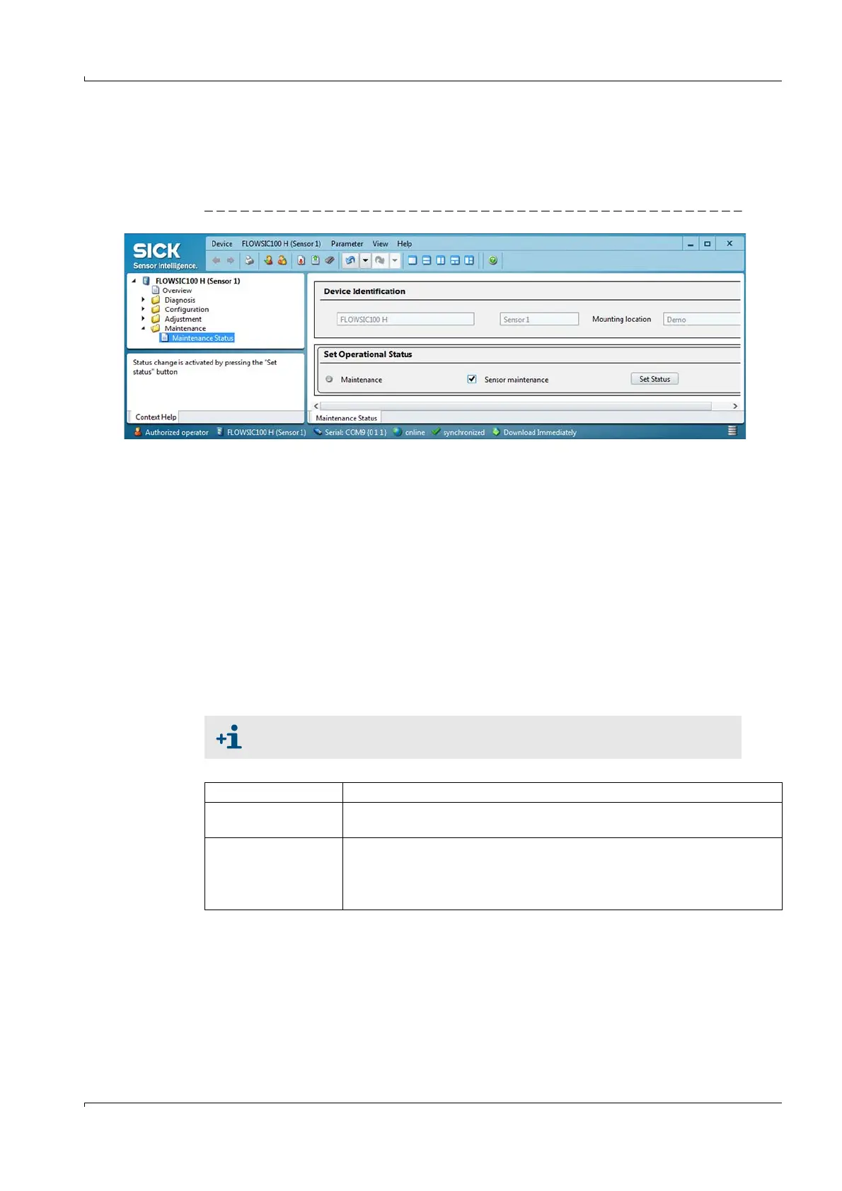
4.2.1 Setting "Maintenance" mode
Open the directory "Maintenance/Maintenance status".
Activate the checkbox "Maintenance" (MCU) or "Sensor maintenance" (sender/receiver
unit) and click "Set Status".
Fig. 100 Switching to Maintenance mode
A control lamp signals the "Maintenance" state as follows:
– In the SOPAS menu "FLOWSIC100 X (Sensor) / Overview",
– In the SOPAS status indicator in the field at the bottom left,
– On the display of the MCU control unit (only for MCU with display option).
4.2.2 Setting the system data parameters on the FLOWSIC100 sensor
Open the device file "FLOWSIC100 X (sensor)" and enter the Level 1 password (
p. 125,
§99).
Set the maintenance mode (
p. 127, §4.2.1).
Basic requirements for every measurement are selecting the unit system (metric or
imperial units) to be used and entering the application parameters (measuring path,
installation angle, cross-sectional area). Select directory "Application Parameters" to enter
settings (
Fig. 101). The settings are uploaded to the FLOWSIC100 after switching from
"Maintenance" to "Measurement".
The following is applicable for application parameters:
The application parameter settings are converted automatically when the unit
system is changed.
Measuring path Distance between the transducers (L in Fig. 102)
Installation angle Angle between the measuring axis and main direction of the gas flow ( in
Fig. 102)
Cross-sectional area
(required to calculate
the volume flow)
Area in range of the ultrasonic transducer that is vertical to the flow direction and
enclosed in the inner duct walls.
If the cross-sectional area changes in the vicinity of the measurement setup,
enter the mean value of the areas between the sender/receiver units A and B.